Solar Power Board
This section covers the parts, hardware, and testing needed to add the Solar Power Board to the CubeSat Simulator board stack.
If you haven't built and tested a CubeSat Simulator board stack, then you should do that first.
This board adds solar power and telemetry to the CubeSat Simulator.
Back to the CubeSat Simulator Home Page.

KiCad files https://github.com/alanbjohnston/CubeSatSim/tree/master/kicad
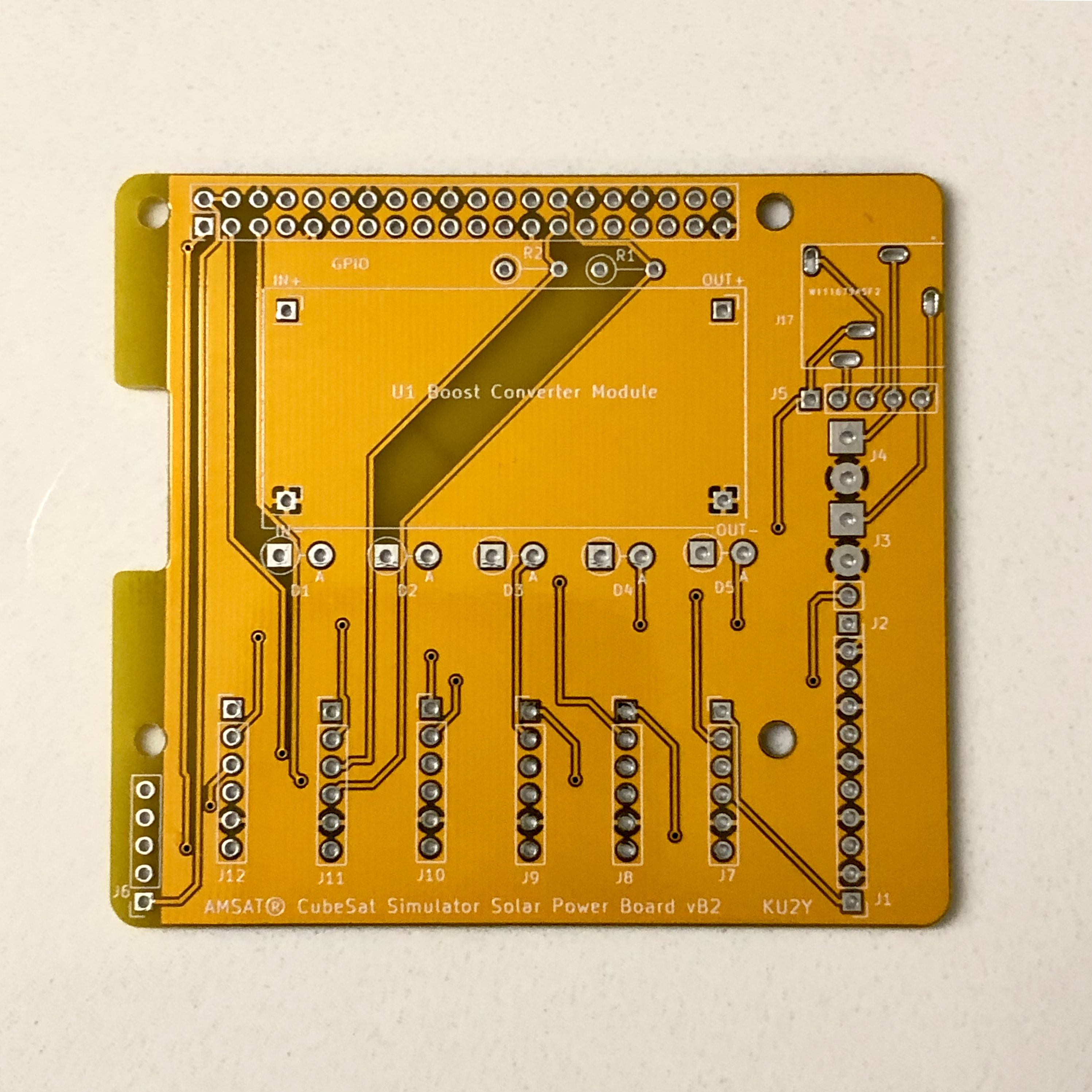
Here is the PCB Design, Beta vB2
Materials:
- 1x AMSAT CubeSat Simulator Solar Power Board PCB vB2
- 1x 40 pin extra long (19mm) male breakaway headers, straight
- 2x 40 pin regular length female headers
- 1x 40 pin right angle male breakaway headers
- 1x Boost module
- 5x diodes, 1N5817
- 2x resistors 4.7k Ohm, 1/4 watt
- 6x INA219 Sensor board
- 10x JST cable pairs, 22AWG wire