note: this is a copy of an article I wrote on medium
I recently added polar alignment to my open source astronomy tool luddcam, which led me down a fun rabbit hole that I'm documenting here. This article might be of interest to any amateur astronomer who has ever wondered how polar alignment works.
When setting up a telescope to take pictures of the night sky, the mount must rotate the telescope exactly in line with the Earth's rotation (both at the same angle and speed). Polar alignment is about matching the angle by pointing at the north celestial pole (NCP), which is pretty close to the North Star. The southern hemisphere doesn't have a bright reference so computer assisted polar alignment is particularly important down under.
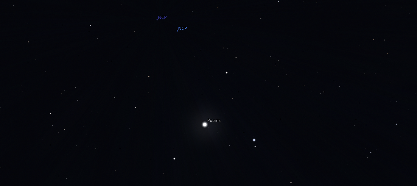
NCP in the years 2000 and 2026 relative to the North Star
Pointing the mount in the general direction of the celestial pole is not nearly enough. As a reference, deep space imaging can require an accuracy ~1/60th of the width of the moon, this cannot be done by eye! Most mounts come with a crude polar scope that can get you in the right ballpark, within a fraction of a degree, but dialling it in can only be done with the help of a camera and computer, the very same gear we're going to use to take pictures.
Most astronomers don't have a camera that points at exactly where the mount is pointing, but they do have the camera that they are taking pictures with and it can be used to infer where the mount is pointing.
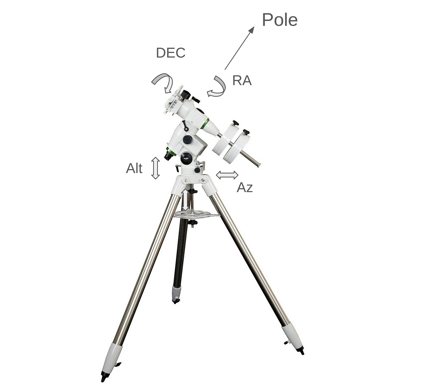
A typical astronomy mount (without the telescope). The Alt and Az is used to point the scope in line with the rotation of the Earth, and the RA/DEC axis are used by the astronomer to find and track subjects.
The typical procedure at the start of a night's imaging is to pick a point near the equator (more on this later) and take an image, then move only in the Right Ascension (RA) axis and take a few more images. From this, the software can figure out where the mount is actually pointing and show on the screen where the astronomer should tweak the alt/az screws of their mount to be better aligned.
The first thing the software has to do is to take those data samples and figure out what they are pointing at. This is done with a technique called plate solving. There's plenty of really good open source solvers out there and luddcam uses a local version of astrometry.net which is optimised to get an answer in under a second.
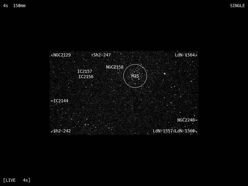
Plate solving in luddcam, finding M35
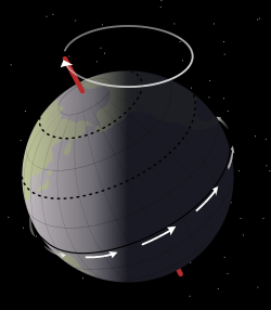
Now we have a list of coordinates in Right Ascension (RA) / Declination (DEC) polar coordinates. For a perfectly polar aligned telescope, the declination will stay exactly the same for the whole night as the motors spin the RA axis at the same speed as the Earth's rotation. But if we're not perfectly aligned, there will be some variation; often going away from us and then coming back as the night goes on.
Even though we have some data points of how the mount is actually moving, it is unfortunately in the wrong coordinate system. All (modern) star charts use the coordinates as they were at noon on the 1st January 2000, the entire Earth has moved since then by about a half moon which is very significant. Thankfully there are many open source tools that can let us know how to correct for this, luddcam uses pyerfa which implements a mathematical model (IAU 2006) that should keep us right for many decades to come.
To apply the transformation we first have to convert our astronomical spherical coordinates into Cartesian (x,y,z) points. This is pretty easy, we convert our RA/DEC into radians and then use some simple trigonometry
theta = radians(ra)
phi = radians(90 - dec)

x = cos(theta) * sin(phi)
y = sin(theta) * sin(phi)
z = cos(phi)
so the north celestial pole is at (0,0,1). But this is still using J2000, we have to rotate everything by what IAU 2006 tells us. Thankfully that is also easy enough and it's just a 3d rotation using some linear algebra (@ in python is a matrix transformation)
p = erfa.pmat06(today)
xyz = p @ [x, y, z]
Here's a real world example
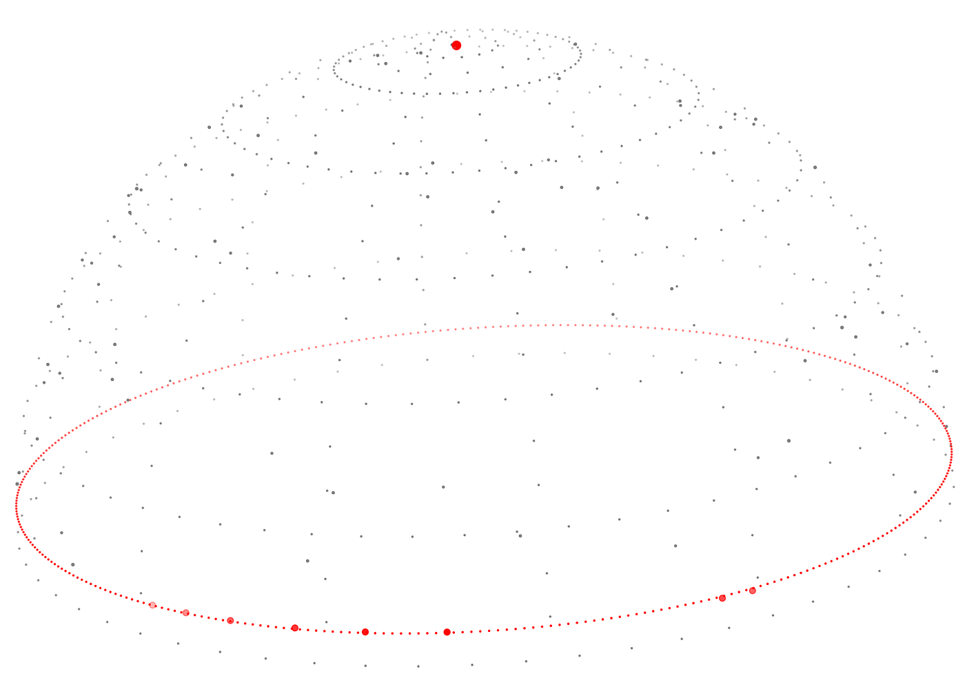
Data captured from luddcam during a polar alignment session (red dots on the line), with their average declination drawn. The pole is drawn at the top. Note that the circle does not exactly go through all the dots, sometimes going above and sometimes below: this is the extent of our mis-alignment, which is enough to move the photography subject out of view throughout the session.
The next task is to find which pole we are actually rotating around, which lets us know how to fix our alignment.
If we find the right pole then the declination of all the samples we took should be exactly the same up to measurement error. Another way of thinking about that is by noting that the dot product between two vectors gives the angle between the points and this angle should be the same for all the data points, the same as saying that the variance is small (the actual angle doesn't matter to us, we only care that they are the same).
So when we have a pole that we want to test, we rotate the true north pole in yaw (declination) and pitch (right ascension)
def rot3d(raw, pitch):
    a = math.radians(raw)
    b = math.radians(pitch)
    return np.array(
        [[cos(b) , sin(a) * sin(b), cos(a) * sin(b)],
         [0      , cos(a)         , sin(a)         ],
         [-sin(b), sin(a) * cos(b), cos(a) * cos(b)]])

mount_pole = rot3d(dec, ra) @ [0,0,1]
and calculate the variance of the declination relative to the mount's pole
dists = [mount_pole @ s for s in xyzs]
return np.var(dists)
Now we have a function that takes a test (RA, DEC) correction and it gives us a number than will be minimum when it points in the same direction as our mount. This is a mathematical area called Optimization Theory.
There are many techniques that can be used here to find a solution but our cost function is so simple that we can actually find a solution by Brute Force Attack, and then zooming in around the best solution until we get the precision we need. Here's an example of that visualised:
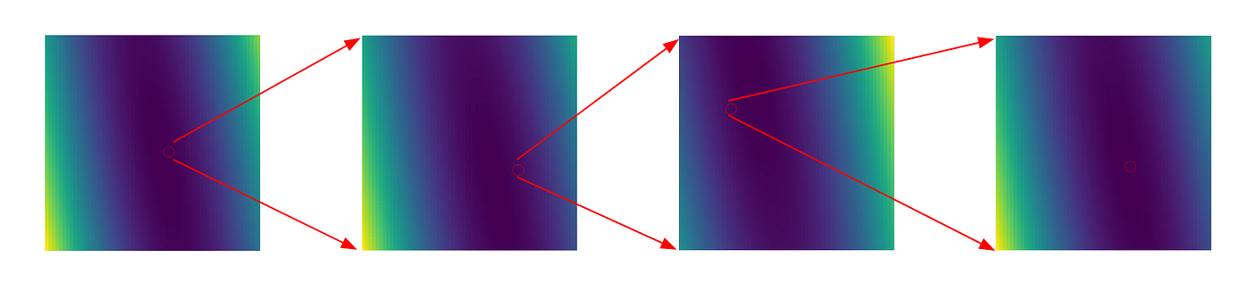
4 stage global optimisation, finding the lowest (bluest) part of the solution space: (RA, DEC) offsets.
Once we found the mount's pole we can visualise what that looks like on the celestial sphere and see that all the sample points do indeed lie on the same circle
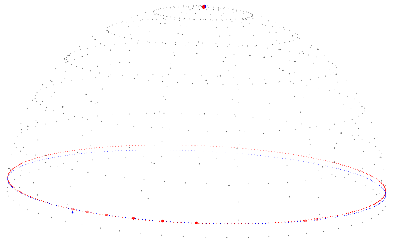
The blue circe shows the constant declination in the mount's reference frame. The blue dot at the top shows the offset between the mount's pole and the NCP (here almost a full degree out).
There is an alternative and more elegant way to find the direction that the mount is pointing. We could fit a plane to many points in 3D, which requires no guess work at all. Once we have the plane, the mathematical trick is noting that the normal of the plane is also exactly the mount direction.
However, since the brute force approach provides an answer in under a second even on a raspberry pi, there isn't much need to really optimise this step. But it's worth thinking about.
Once we know where the true pole is relative to us, that gives us the yaw and pitch that we can apply to move from the true pole to our mount's pole. So all we need to do is apply the opposite of that transformation (the transpose) to our current location in the sky (remembering about precession) and it gives us a point to aim at!
t = rot3d(dec_err, ra_err)
x, y, z = p.T @ t.T @ current

dec = 90 - degrees(acos(z))
ra = degrees(atan2(y, x)) % 360
which we can then show to the user, along with an estimate of how far off the pole they were
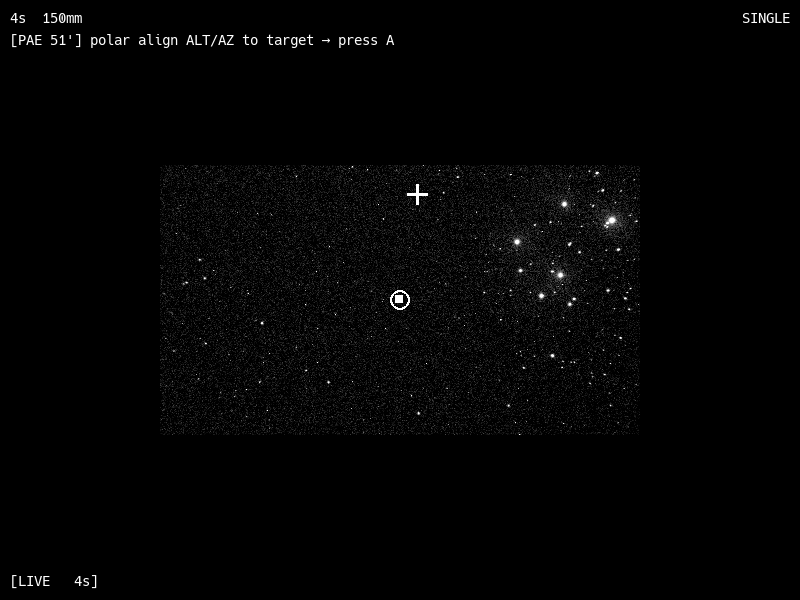
Screenshot from luddcam after polar alignment. The estimate of the error here is 51' (arcminutes) which is almost a whole degree out. The user must move their alt/az until the circle goes over the crosshairs. The square shows where the alignment started, which is super useful when you forget to use the alt/az and accidentally start moving the ra/dec… this stuff is complicated in the dark!
The whole process needs to be done pretty quickly, otherwise the target can move. Accounting for this is pretty complicated so luddcam doesn't do anything, and I doubt any other software would too. As a rule of thumb, if you need to deal with something for 5 minutes or longer (finding allen keys or a red light) it's best to just start over… not to even mention the periodic error of the mount.
There's a final and major piece of the puzzle that places a practical limit on how accurate we can track the stars and that's atmospheric refraction. The deflection is zero looking directly up (the zenith), and ~1/60 of a degree at 45° (halfway to zenith), getting progressively worse the closer we get to the horizon where it gets as bad as half a degree (the width of the moon!).
source: wikipedia

If we know the user's location and time, we can try to correct for atmospheric distortions but the stars are going to be distorted by refraction no matter what we do.
The best way to get aligned to the true axis of the Earth is to use a declination that crosses your local zenith, e.g. I'm at 56° latitude so I should align to a declination of 56° and never take data samples below 45° apparent altitude. From a practical point of view, we have to be careful about the final sample, because the closer to the zenith the telescope is pointing, the more the azimuth controls on the mount's polar wedge will rotate the field of view, and it's like doing a 3 point turn in a tight space. A workaround is to make sure that your final sample point is always at about 45° in the sky instead of at its highest point, so that the alt/az controls actually move the camera's view in a predictable way.
Instead of aligning with the true axis of rotation of the Earth, Luddcam recommends taking polar alignment samples close to the declination of the image subject for that night, so at least we're aligning to the apparent axis of the target (even though it's not fixed).
This advice may be sacrilege to many; the common wisdom is to take samples near the equator. But that's incorrect unless you are imaging deep space objects near the celestial equator or you happen to live near the terrestrial equator. But hopefully you now understand where to point your telescope to polar align and set some realistic expectations of how accurate unguided tracking can be, especially further away from the zenith.