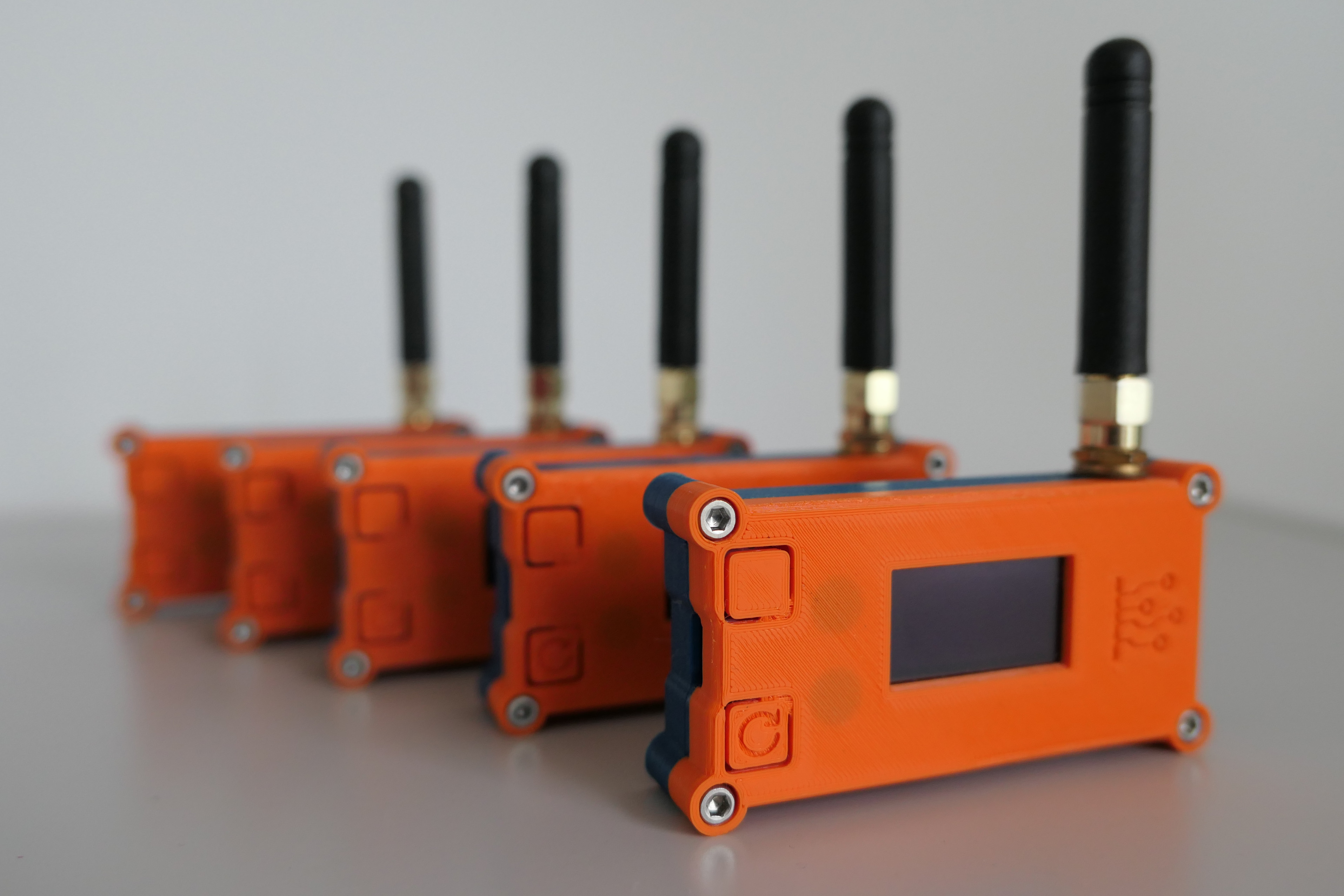
This repository contains the source code for the wM-Bus Gateway, a device that integrates Wireless M-Bus media meters with other systems.
⚠️ Warning:
Do not power on the device without the antenna connected – this may damage the radio module.
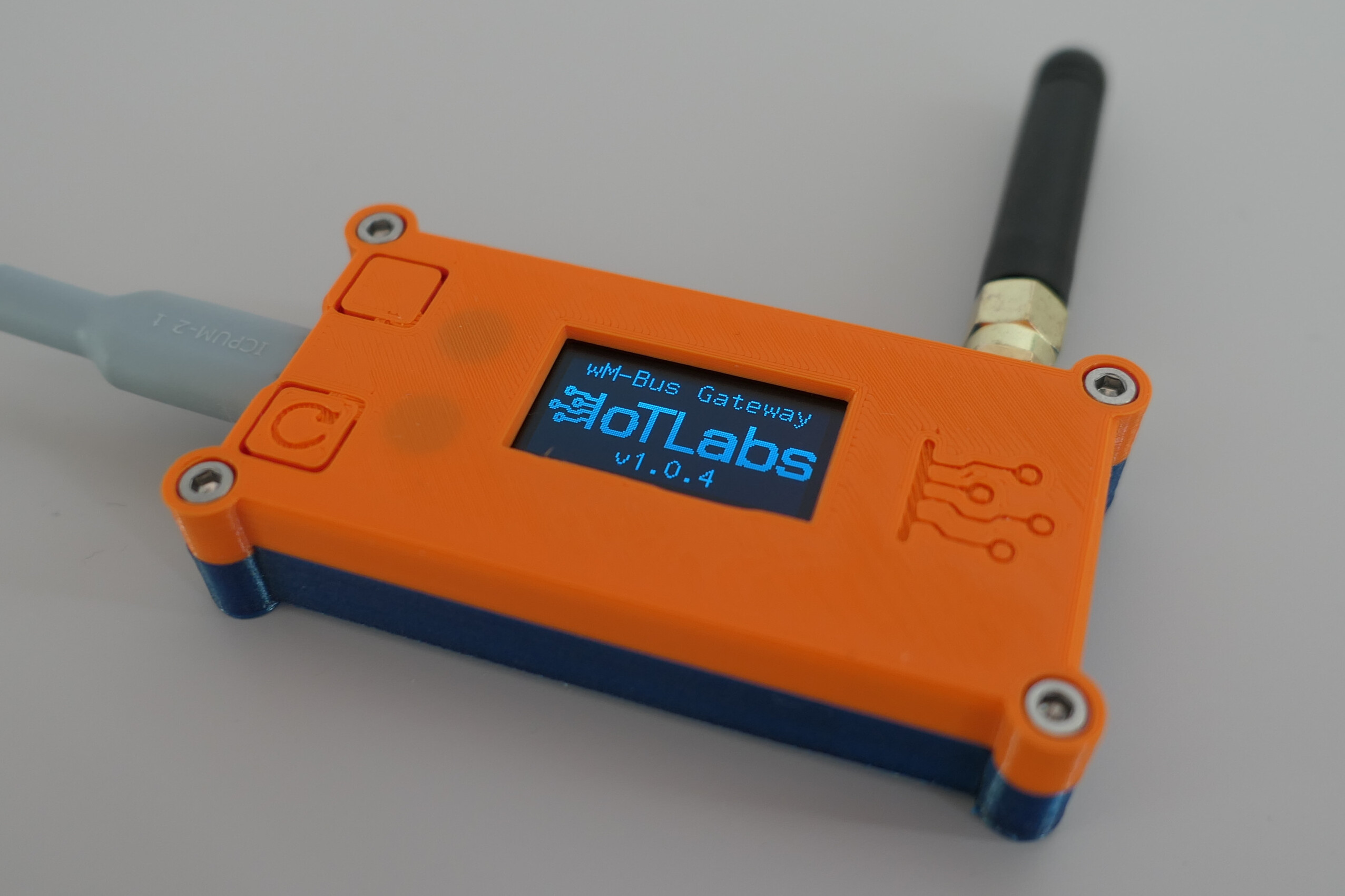
- 🟦 The device has two buttons:
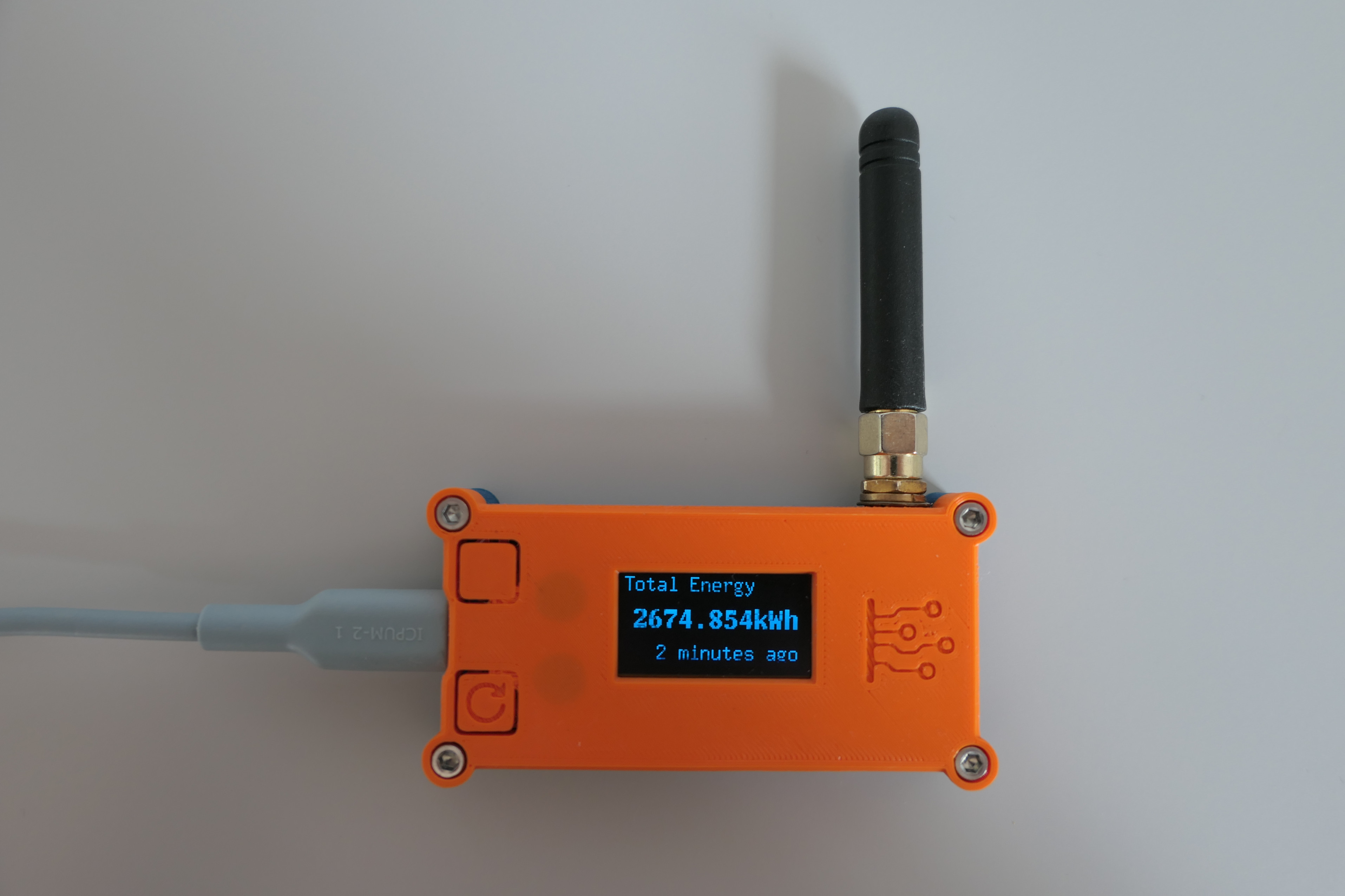
- Top button – used to switch pages on the display.
- Bottom button – used to reset the device.
- 📶 Reception of the wM-Bus datagram is signaled by a fast blinking of the built-in LED.
- ESPHome Dashboard (can be used as a Home Assistant Add-on or Python package)
-
Power up the device with a USB cable. You may use your computer or a USB power adapter.
-
Connect the device to your Wi-Fi network using one of the following methods:
- 🌐 via device's Wi-Fi access point:
- Connect to device's access point (SSID:
IoTLabs wM-Bus Gateway, no password) - Open
http://192.168.4.1in your web browser - Enter your Wi-Fi credentials and click Save.
- Connect to device's access point (SSID:
- 🔵 via Improv BLE:
- Open Web Tools with a device and browser supporting Bluetooth Low Energy (BLE), e.g. a mobile phone with Google Chrome or Edge.
- Click Connect in the
Improv via BLEsection. - Select your device from the list.
- Follow the instructions to connect the device to your Wi-Fi network.
- 🟠 via Improv Serial:
- Connect the device to your computer using a USB cable.
- Open Web Tools with your computer and a browser supporting Web Serial API (e.g. Google Chrome or Edge).
- Click Connect in the
Improv via Serialsection. - Select your device from the list.
- Follow the instructions to connect the device to your Wi-Fi network.
- 🌐 via device's Wi-Fi access point:
-
When your device switches to the selected network (the currently connected network name is shown on a dedicated display page), go to the ESPHome Dashboard where you should see a newly discovered device and click the Take Control button.
-
In the following popup window, type the desired device name and click Take Control.
-
In the next two popup windows, click Skip and Close.
💡 Tip:
You may also install new firmware at this point, but ESPHome will build factory firmware which is already installed on the device. -
Click the Logs button for the already added device in the ESPHome Dashboard and choose the appropriate connection method (wireless if not connected via USB, or wired if you are).
🖱️ Tip:
For testing, you may click the top button on the device to switch display pages and see logs about these events.Wait some time to receive a wM-Bus datagram and see it in the logs. You will get logs like this:
[16:29:10][W][main:057]: Meter ID: 12345678... [16:29:10][W][main:060]: Frame: https://wmbusmeters.org/analyze/be44ed1... -
Click or copy and paste the link from the logs to your browser to analyze the received datagram. At wmbusmeters.org you will be able to check your decryption key (if your meter is encrypted) and see all data fields available to decode from the datagram.
-
When you identify your meter ID, decryption key, and fields you are interested in, you can edit the device configuration in the ESPHome Dashboard.
-
In the section
wmbus_meterset:meter_idto your meter IDtypeto the driver name in wmbusmeters- optionally
decryption_key idas a label for referencing in other YAML sections
-
In the
sensorsection, create a sensor for each field you want to decode. Each sensor needs:parent_idto link to the specific meterfieldto specify which decoded field to use- Other parameters are specific to ESPHome; see the ESPHome documentation for details.
-
-
When you finish editing the configuration, click the Install button in the ESPHome Dashboard and choose your preferred installation method (wireless or USB).
-
After installation, go to your Home Assistant instance and add the device with ESPHome integration.
Typically, it will be automatically discovered, but you can also add it manually on the Integrations page by entering the device IP address.
You can find the example in the `blueprint.yaml` file in the root directory of this repository. This file is also automatically imported into your ESPHome Dashboard when you add the device for the first time.
You can change the visible unit of measurement in the `sensor` section of the ESPHome configuration. For example, to change from `kWh` to `MWh`:
unit_of_measurement: "MWh"
filters:
  - multiply: 0.001
This will adjust the value and display the correct unit.
By default, the built-in LED blinks (10 blinks for one second) when a wM-Bus datagram is received.
You can change this behavior by overriding the on_frame automation in the wmbus_radio section of the ESPHome configuration. For example, to disable it completely you may use following cofiguration:
wmbus_radio:
  on_frame: !remove
If you want to change the LED blinking pattern, you can use the following example:
wmbus_radio:
  on_frame:
    then:
      - repeat:
          count: 2
          then:
            - light.turn_on: wmbus_gateway_status_led
            - delay: 500ms
            - light.turn_off: wmbus_gateway_status_led
            - delay: 500ms
It will blink the LED twice with a 500ms interval.
You may also blink LED for specific meter datagrams. For example, to blink the LED only for a specific meter ID:
wmbus_radio:
  on_frame: !remove

wmbus_meter:
  - id: my_meter
    ...
    on_telegram:
      then:
        - turn_on: wmbus_gateway_status_led
        - delay: 100ms
        - turn_off: wmbus_gateway_status_led
  - id: another_meter
    ...
    on_telegram:
      then:
        - repeat:
            count: 5
            then:
              - turn_on: wmbus_gateway_status_led
              - delay: 100ms
              - turn_off: wmbus_gateway_status_led
              - delay: 300ms
In this example, the LED will blink once for my_meter and five times for another_meter.
For more complex LED patterns, you may use the script component in ESPHome. It allows you to define parameters (number of blinks, delay, etc.) and create reusable fragments of code for different events as demonstrated in ESPHome documentation.
You may use wmbus-gateway-esp32.factory.bin available in the Releases to flash the device with factory firmware.
A simple web flasher based on ESP Web Tools is available at:
👉 https://iotlabs.pl/en/tools
More info about the device can be found at:
👉 https://iotlabs.pl/en/wm-bus-gateway/