Hardware
The on-board LED provides visual feedback about connection and traffic status:
- LED off: ESP32 is not connected to upstream AP
- LED on (steady): ESP32 is connected to upstream, no traffic
- LED flickering: ESP32 is connected, traffic is flowing through the router. The flickering intensity is proportional to the traffic volume — heavier traffic produces more intense flickering
By default, the LED is disabled. To enable it, configure the GPIO pin for your board:
set_led_gpio 2          # Set LED to GPIO 2
set_led_gpio none       # Disable LED (default)
set_led_gpio            # Show current setting
Changes take effect after restart.
| Board / Chip | Default LED GPIO |
|---|---|
| ESP32 DevKit v1 / WROOM | GPIO 2 |
| ESP32-S2 | GPIO 2 (varies) |
| ESP32-S3 DevKitC | GPIO 48 (RGB) |
| ESP32-C3 DevKitM / SuperMini | GPIO 8 |
| ESP32-C6 DevKitC | GPIO 8 |
| NodeMCU-32S | GPIO 2 |
| Lolin D32 | GPIO 5 |
| Lolin32 Lite | GPIO 22 |
Note: Some boards have active-low LEDs. ESP32-S3 often uses GPIO 48 for an addressable RGB LED (WS2812) which may require different handling.
The firmware supports a 72x40 pixel (0.42") SSD1306 OLED display over I2C. This is specifically designed for the small I2C OLEDs found on certain ESP32-C3 mini boards. Other display sizes or drivers are not supported.
The display shows:
- AP SSID
- STA connection status and RSSI
- STA IP address
- Number of connected clients
- Sent/received traffic in MB
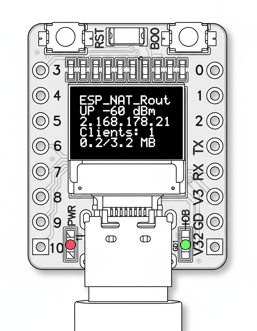
The OLED display is disabled by default. Enable and configure it via the serial console:
oled enable              # Enable OLED display (requires reboot)
oled disable             # Disable OLED display (requires reboot)
oled gpio <sda> <scl>    # Set I2C pins (default: SDA=5, SCL=6)
oled status              # Show current configuration
The default I2C pins (SDA=5, SCL=6) match the typical wiring on ESP32-C3 mini boards with built-in OLED.
The XIAO ESP32-C6 board has a hardware RF switch to select between the built-in ceramic antenna and an external antenna:
set_rf_switch_XIAO 0    # Built-in ceramic antenna (default)
set_rf_switch_XIAO 1    # External antenna
Uses GPIO3 (RF switch enable) and GPIO14 (antenna select). The setting is saved to NVS and applied on every boot.
You can factory reset the ESP32 NAT Router by holding the BOOT button for 5 seconds. This erases all settings stored in NVS (WiFi credentials, port mappings, DHCP reservations, ACL rules, passwords, etc.) and restarts the device with default configuration.
The BOOT button GPIO is selected automatically at compile time based on the chip:
| Chip | BOOT Button GPIO |
|---|---|
| ESP32, ESP32-S2, ESP32-S3 | GPIO 0 |
| ESP32-C3, ESP32-C2, ESP32-C6 | GPIO 9 |
- Press and hold the BOOT button on your ESP32 board
- If an LED is configured, it will rapidly blink to indicate the button press is being detected
- Continue holding for 5 seconds
- The device will erase all settings and restart automatically
After reset, the ESP32 will boot with default settings (open AP with SSID "ESP32_NAT_Router").
-
Serial console: Use the
factory_resetcommand -
Full flash erase:
esptool.py -p /dev/ttyUSB0 erase_flash(also erases firmware)