Pin 3 to 13 as well as A0 to A5 on UNO are digital I/O, they can be set as either input or output mode. To do that, write pinMode(PIN_NUMBER, MODE) in setup() function block, you can also change the pin mode in the loop if needed. There are three modes you can use for pinMode, OUTPUT, INPUT, and INPUT_PULLUP.

In this example, we will use the on board LED which is internally connect to pin 13. You can check at the small LED next to pin 13.
void setup(){
    pinMode(13, OUTPUT);
}

void loop(){
    digitalWrite(13, HIGH);
    delay(100);
    digitalWrite(13, LOW);
    delay(100);
}
Here we set pin 13 to output mode, which it can write to be HIGH (5 volt) or LOW (0 volt) by using digitalWrite(PIN_NUMBER, STATE). The delay() function will pause the system to the given number of miliseconds. In this example, the LED will stay on for 100 ms and OFF for another 100 ms repeatedly.
The on board LED is a good way to troubleshoot your microcontroller if it is still working.
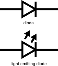
LED is acronym for Light-Emitting-Diode, useful for low power and efficiency light source in small project. It is also a diode such that it has a anode and cathode, meaning it only light up in the correct polarity. The advantage of being a diode is that, while placed with reverse-polarity, you actually will not damage the LED , given the voltage is below its breakdown voltage. Because a diode behave like a insulator in the reverse bias mode.
It is important to add a so-call current limiting resistor to ensure the LED does not draw infinite amount of current. A common resistance is 330 Ohms. Sparkfun has a really good tutorial for LED, check it out if you want to learn more.
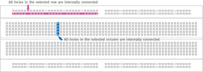
Breadboard is a very common tool for prototyping electronics and circuitries, you can just plug in your components with wires to complete and test out your circuits without needing to solder. Note how the breadboard are internally connected, the long edge has the power rails, usually for power and ground lines, and then at the middle the rails are running in perpendicular direction. Sparkfun has a detail tutorial for breadboard, check it out if you are interested.
To wire your external LED, follow the circuit below. Just connect the digital output pin in series with LED, resistor, and goes back to ground pin of your Arduino.

void setup(){
    pinMode(7, OUTPUT);
}

void loop(){
    digitalWrite(7, HIGH);
    delay(100);
    digitalWrite(7, LOW);
    delay(100);
}
You should observe the same LED blinking pattern.
Now we can try to expand the circuitry by including more LEDs. Follow the diagram below to connect 6 LEDs to pin 2 to pin 7.

void setup(){
    pinMode(2, OUTPUT);
    pinMode(3, OUTPUT);
    pinMode(4, OUTPUT);
    pinMode(5, OUTPUT);
    pinMode(6, OUTPUT);
    pinMode(7, OUTPUT);
}

void loop(){
    for ( int i = 2 ; i < 8 ; i++ ){
        digitalWrite(i, HIGH);
        delay(100);
    }
    for ( int i = 2 ; i < 8 ; i++ ){
        digitalWrite(i, LOW);
        delay(100);
    }
}
In this example, the LEDs will light up one by one in order and then turn off one by one. We implement a for-loop structure to iterate through each pin, in this case we started from pin 2, and then increment by one at a time till pin 7.
You can try write your code to make the LEDs to light up in different patterns.