Date: 22-07-2025
This project demonstrates an RFID Attendance System based on the STM32F103C8T6 microcontroller. The system reads RFID tags using an RC522 module and logs attendance data with a timestamp from the DS1307 RTC. The information is displayed on a 1.3" I2C OLED and logged to a PC using a UART-based Python data logger.


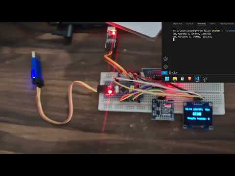
click on the image to play
This project is built to automate the attendance recording process using contactless RFID cards. Each scanned card displays the associated user details and timestamp on the OLED display and transmits the data to a computer via UART.
The system is suitable for classrooms, offices, or secured entry areas where monitoring and logging personnel activity is important.
- Developed using STM32CubeIDE with STM32 HAL libraries for peripheral interfacing.
- The entire setup was powered by a UART-to-TTL USB module, which also served as the serial communication link to a Python script in Visual Studio Code.
- Tested using 3 RFID cards, each having a unique UID to simulate multiple users.
- Timestamp from DS1307 RTC was used to record check-in/check-out time accurately.
- A compact 1.3" SSD1306 I2C OLED was used for quick visual feedback.
- Output format example:
- Real-Time Attendance Logging using RFID cards
- OLED Display Output for user identification and timestamp
- RTC Timestamp (from DS1307) ensures accurate logging
- UART Communication for data logging to PC
- Python Logger captures data to CSV on the PC
- Minimal Power consumption via USB
- 1 × STM32F103C8T6 Blue Pill Board
- 1 × RC522 RFID Reader Module
- 1 × DS1307 RTC Module
- 1 × 1.3" OLED Display (I2C, SSD1306)
- 1 × UART-to-TTL USB Converter
- 1 x stlink v2
- 3 × RFID Cards/Tags
- Jumper Wires, Breadboard
- Power Source: USB from UART module
- Initialization:
- On boot, the OLED displays project title and waits for card scan.
- Card Detection:
- RC522 detects a valid RFID tag.
- UID is checked against pre-defined users.
- Time Logging:
- DS1307 provides the current date and time.
- OLED displays:
Time: 12:35:27 Anandhu S (EMP069) Entered
- Data Transfer:
- The same string is sent via UART.
- Python script captures and appends to a CSV file.

This diagram shows the connections between STM32F103C8T6, RC522, DS1307, OLED, and UART module.
- RCC -> High Speed Clock (HSE) -> Crystal/Ceramic resonator
- SYS -> Debug -> Serial wire
- I2C1 for oled display (should be in fast mode)
- I2C2 for rtc module in normal mode.
- SPI1 for rc522 module, full duplex master, (in configuration - Prescalar (baud rate) = 8)
- USART1 - Asynchronous, set baud rate according to your need. (mine 115200)
- set PC13 as gpio output for using in-built led
- set PA4 as gpio output
- set PB0 as gpio output
- Create a new project and configure it as mentioned in the cube ide configuration.
- Under project name -> Core-> there will be 'inc' and 'src' .
- Copy the .h files to inc folder and .c files to the src folder.
- Copy the contents of 'main.c' contents to your main.c file.
- Build and make sure there's no error and warnings.
- Create the hex file.
- Right Click project name, properties, c/c++ buil, settings, mcu post build outputs, tick create hex file, apply and close.
- Flash the hex file using stmcube programmer or stlink utility, (some clone boards cannot be flashed directly from the stmcube ide).
- Clone the firmware source code into STM32CubeIDE.
- Connect modules as per the connection diagram.
- Flash the code to the STM32 board using stlink v2.
- Connect the uart-ttl connector to USB port and check which COM port it is connected.
- Run the Python logger script in Visual Studio Code.
- The output can be observed in the output terminal of the python code.
- Scan RFID tags to log and display attendance info.
- STM32CubeIDE (Firmware Development)
- STM32 HAL Libraries
- STLINK Utility
- Python (Serial Communication and CSV Logging)
- Visual Studio Code (Python script development)
- Add EEPROM or SD card backup logging
- Introduce Wi-Fi (ESP8266) for cloud sync
- Add Buzzer/LED alert for duplicate scans or unauthorized cards
- Include GUI Interface on PC for data visualization
/STM32– STM32 codes (inc , src, main)/Python_codes– Python script for UART CSV logging/Images & videos– Diagram, video
- The board is powered directly via the UART module.
- RTC battery backup ensures timekeeping even when powered off.
- Tested on 22-07-2025 with 3 unique cards.