Voltage Divider
For both methods you will a need a thermistor. We recommend getting one on the M3 stud, since they can easly be fastened without fear of damaging it (the glass bead thermistors are extremely fragile).
This is the very simple option, if you are happy to solder onto your mainboard. You will need:
- a surface mount 4.7k Ohm resistor.
- Solder tools and wires
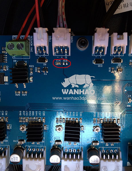
- Locate the R15 (on newer mainboards) - it should be right at your TEMP1 connector (where you plug in the wire leading to your temperature sensor). It is close to the C14 capacitor. There should not be any resistor on it - we will now add it.
- This R15 sits between the +5V and the S coming from the sensor.
- Now solder the 4.7k Ohm resistor to this spot made for it. Be carful not to damage the other parts or keep heating a spot for too long - rather get help than damage the mainboard.
- Remove the thermocouple and its amp from the nozzle and the pipe respectively, and connect your 100k NTC thermistor to the nozzle.
- The thermistor needs to be placed between the Ground (aka -) and the S (signal), so you can modify your 3 wire cable to accomodate only the outer 2 wires to the thermistor (center is the +). A thermistor does not care which side is the Signal and which is Ground.
This is also a simple option with the added benifit of not modifying your mainboard in any way. You will need some Strip Board (or other compatible pc board), a 4.7k Ohm resistor, a jumper.
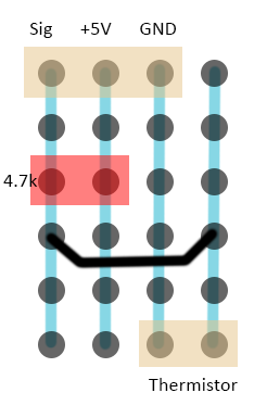
Replicate this image with your stripboard:
- The dots are the holes in the stripboard.
- Blue lines are the strips of the board, and is below the board (image from the top / non-conductive side).
- The Red is the 4.7k Ohm resistor - I uses a through hole resistor for this (important it needs to be between + and S)
- The black is the jumper (connecting the signal to the side running to the thermistor) - technically if you do not want to use a connetcor for the thermistor, you can solder its wire directly to the Sig strip.
- The Beige is the connectors JST-XHP (a 2 pin for the thermistor and a 3-pin for the wire coming from the mainboard) - this is made to take the original wire directly (so that it can be undone).
A voltage divider allows the mainboard to read the resistance of the thermistor. It works by comparing the voltage over the thermistor with that of a known fixed resistor (together they will always be 5V).
I have created this firmware, since I needed it. I continue to improve on this firmware (adding more features, optimizing other features and settings), and will also offer support on it (through the Wanhao Google Group). All of this takes a lot of time and effort.
If this firmware or my support helps you in any way, please considder a small donation.
