If you were to take a look at many of my repositories, you'll find that for someone who doesn't actually love having a bunch of LEDs on things, I seem to tell people to use a whole lot of them. There are projects where I've gone through several revisions, installing different colours on them so that I'd instantly be able to tell them apart. What you won't find is a lot of datasheets, because where I shop - you generally get a bag full of them, and nothing that you would call a datasheet. Perhaps I should shop in better places, but I just can't stop myself. And as for the end result, there are times where I'm straight up guessing at which value resistor to put in series with it. Sometimes it fails to light up, sometimes it'll blind people in the next room, and from time to time I get them just right because I had found the same bag of LEDs.
And after doing that for almost a decade, I knew it was time! It was time to change, it was time to get a variable bench power supply and a proper breadboard. Realizing that such PSUs cost far more than I would be willing to pay, and that I would never find a breadboard that I would consider "good", I did what I always do: I designed something. I call it the LED Tuning Board.
Does it tune your LEDs? No. What it does is give you a way to quickly plug in various types of through-hole LEDs, and then allows you to quickly go through various combinations of resistors until you find something that YOU will find comfortable. Because comfortable is what you'll be willing to have sitting on your desk, no matter if that desk is in a brightly lit studio or the dank type of basements that I regularly seem to enjoy dwelling within.
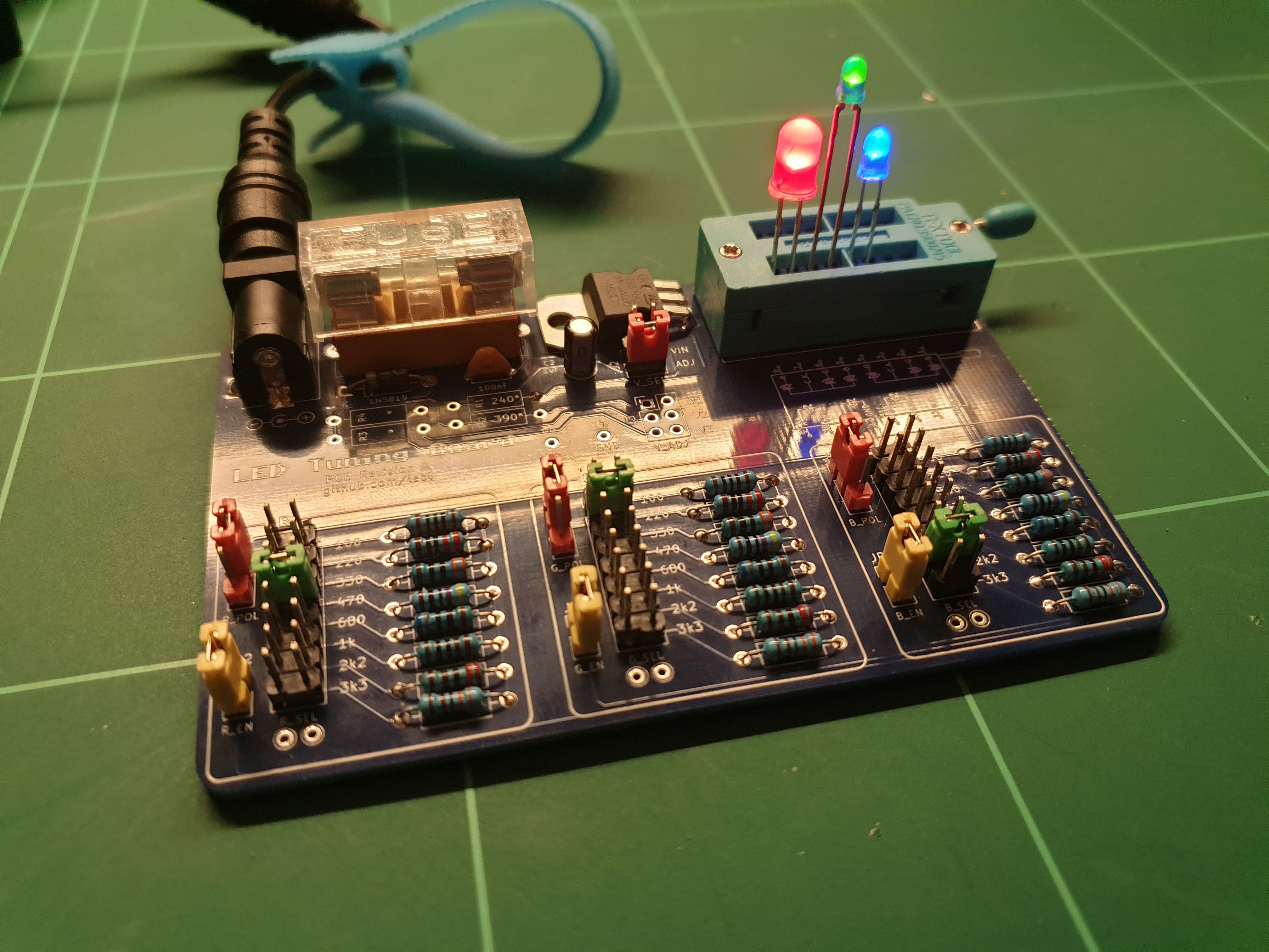
At some point I wanted to do a whole video on the topic of the LED Tuning Board, but I miserably failed at coming up with sufficient amounts of puns in order to pull off 20 minutes worth of soldering an LED in different ways. Until I do, here's a short clip of me showing the thing in as short a time possible. RGB LEDs are a feature of it, but necessarily so - they're just three LEDs combined into the physical space of one. There are three banks of resistors, one for each - with a jumper next to it that hooks that end up to VCC or GND. Add more than one jumper to a single bank in order to put resistors in parallel, add a few DuPont wires between pins and you can easily put a banks resistor value in series with that of another bank.
Truly exciting stuff! And on that note, I also put a commonly available fuse on the board - for when things become slightly too exciting.
Soldering together the few components should be easy going as long as you have access to a reasonable set of tools, personally I'm using a cheap soldering station with adjustable temperature so there's no need really no need to offer up your hard-earned cash to the old Norse god, Hakko. Hakko is actually a well-known brand, not a Norse god as previously stated. I meant that as a joke, so please don't send me brand new Hakko gear as punishment (I would just end up using it). Go expensive if you want to, not because that one guy on the Internet told you to. Personally I prefer using 60/40 soldering tin, mostly as the lead-free stuff makes the job a lot harder when you're just getting into the hobby of soldering things together.
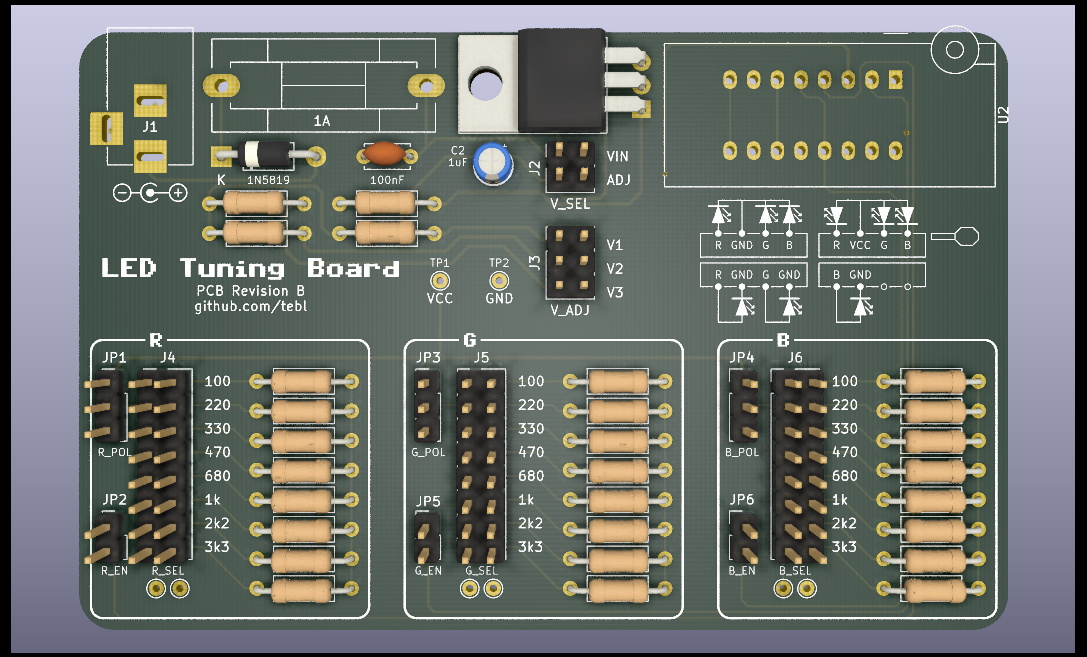
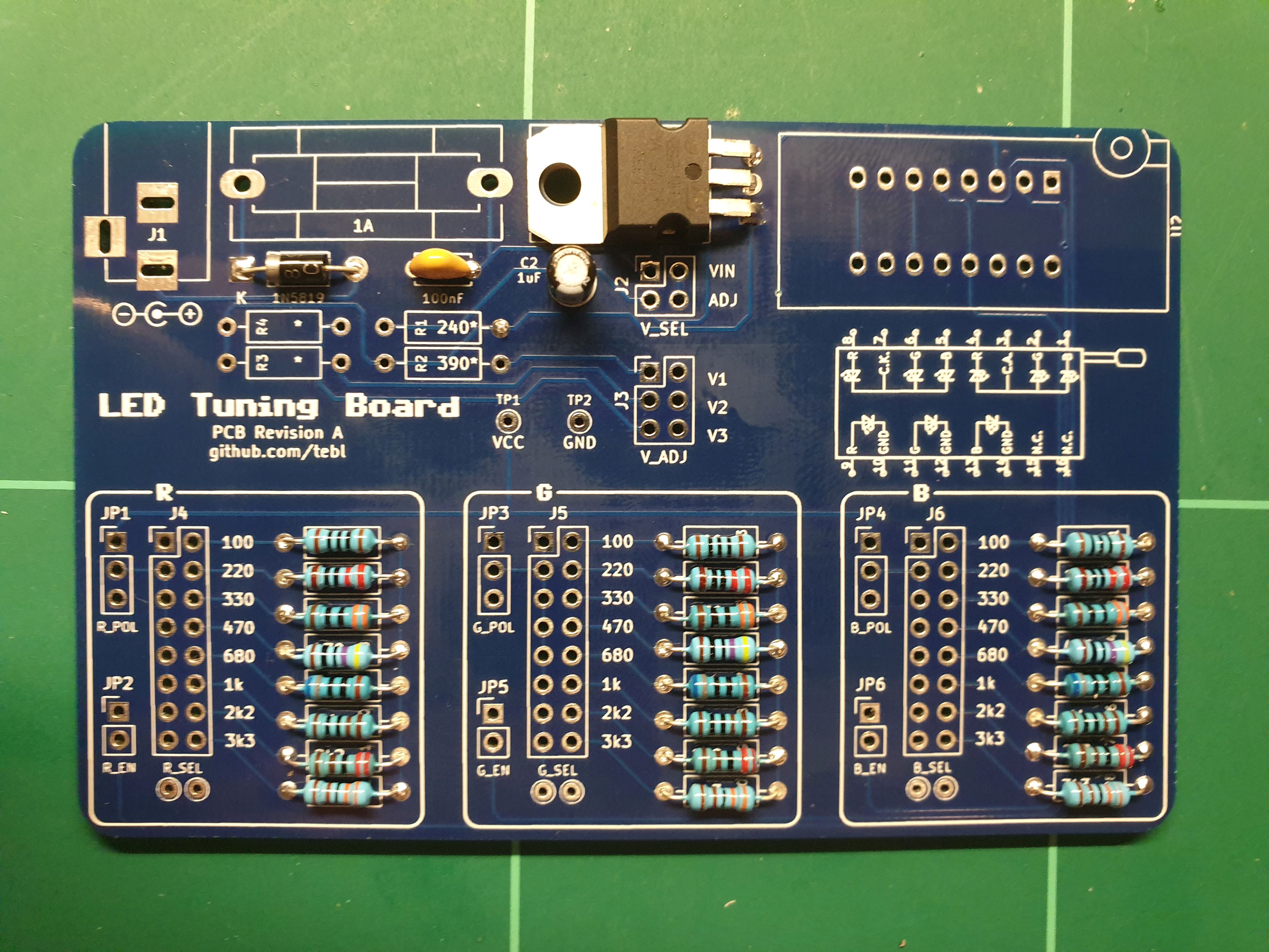
Do, however, make sure to start by studying the PCB by itself. Both sides, perform dry fits where needed so that you have an idea of where everything should go. The latter is because removing a components is always a lot harder than getting it right in the first place. In particular, take care when it comes to the orientation of polarized components - these include electrolytic capacitors and diodes (match the orientation exactly, study the gallery images for reference).
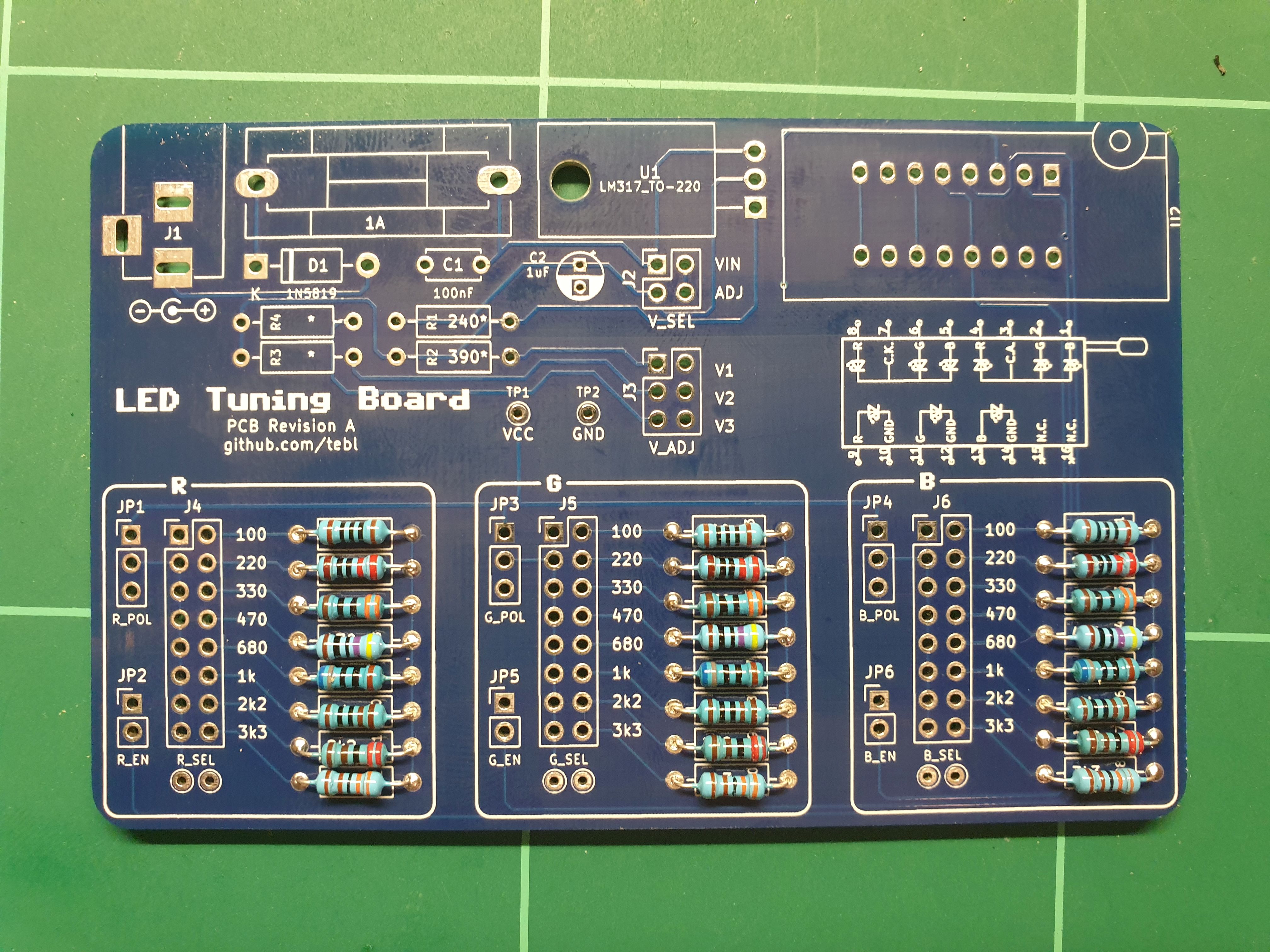
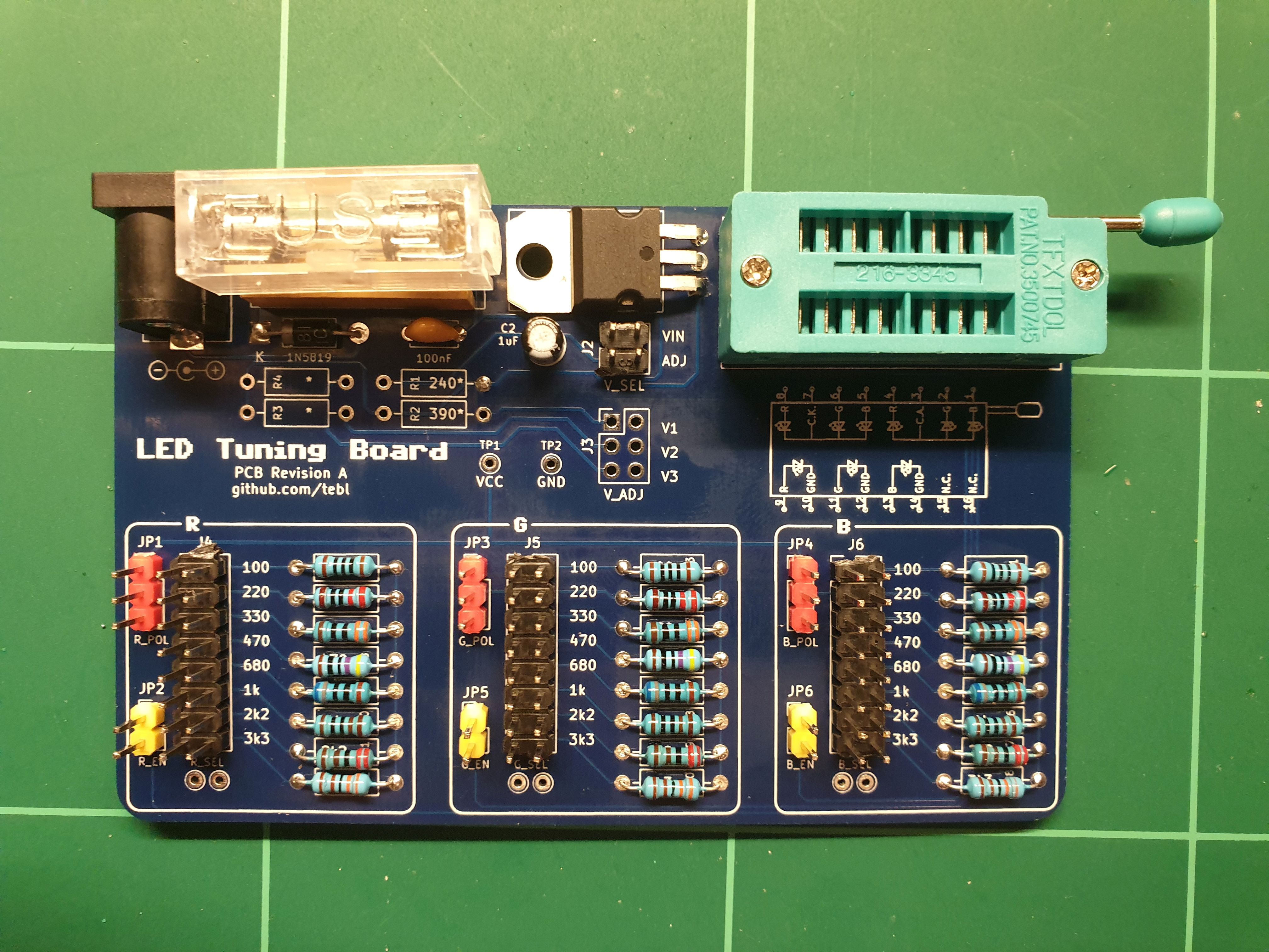
As for a first step though, I've just gone ahead and added the resistors to each of the resistor banks. While you could adapt things slightly by changing out some of the values, these are the most common values that anyone would probably have available in their parts-bin. Each of them should match up with a step on the pin header block next to it.
As for the remainder of the installation, I went in the direction of building a different version of the one covered by the schematic. Mainly because I did not have the LM317 variable regulator available when building it, so I instead made changes to the circuit by building one with a 3.3v regulator instead. Check out the proceeding subheadings for details on the construction of either of them.
Before doing all that, I did add a 1N5819 Schottky diode - that's there to keep things from exploding if you were to plug in a power supply with the incorrect polarity. For that you also need to ensure that you actually install it the right way, meaning that the little silver stripe should match up with the white stripe on the board.
My choice of the LD1117AV33, a 3.3v regulator, was based on the thorough research of finding one in my parts-bin then throwing it in there. As they're not entirely the same, we'll need to make a few small adjustments when attempting to use it.
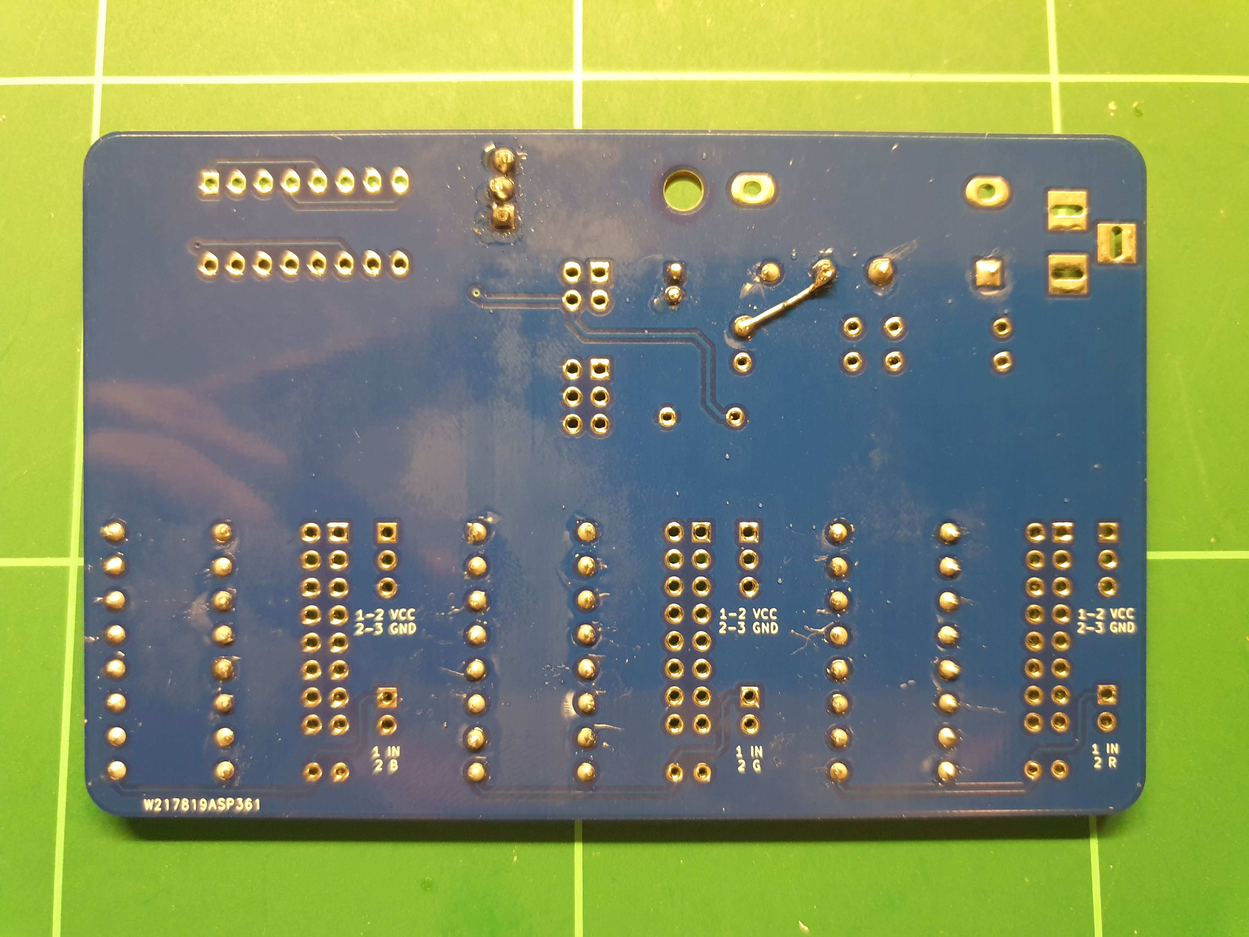
The first change is that C2 should have a greater value than the one printed, going up to 10uF instead of the sticking with the 1uF as marked. The resistors marked from R1 through R4 have also been skipped, we also no longer have a need for J3. We also need to install a small piece of wire on the back, some of the leftover clippings from one of resistors will be perfect.
❔ The LD1117A-series of volage regulators have a wide range of output voltages available, I've simply picked 3.3v as with a 5v power input I end up with the two I need. If you want something else, there's also the LD1117AV50 in case you explicitly wanted one that has 5v on the output.
The LM317 voltage regulator is the one I had in mind when building this version of the PCB, its main selling point is that we can easily generate several other voltages based on the choice of resistors installed on the board. With a common resistor (R1) as its base, we will get different selectable output voltages (V1/V2/V3) depending on the value of resistors R2, R3 and R4 - one for each of the generated outputs. One has been filled in for you along with a set base, that's R1 at 240 Ohm and R2 at 390 Ohm for a V1 = 3.28v.
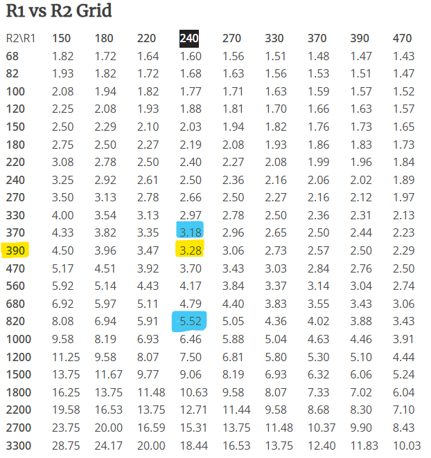
That sounds like a lot of math that we need to do, but if you're going by the one suggested - we've already chosen a base resistor value (R1 = 240 Ohm). Basically we just need to pick whatever we want for R3/R4 by going up or down on the table, just know that we won't be able to generate a higher voltage than what we sufficiently provide it with. If you want to understand how exactly it works, either consult the datasheet included or you can go to the source of the table at reuk.co.uk for all of the relevant mathematical questions.
With all of the neat details on the choice of voltage regulators taken care of, hopefully explained sufficiently that you know what was going on the whole time. As for the pictures we've been covering the installation of a fixed regulator, so when moving forwards we need to keep in mind that J3 will not be needed. You will, however, need it if you went with the variable option.
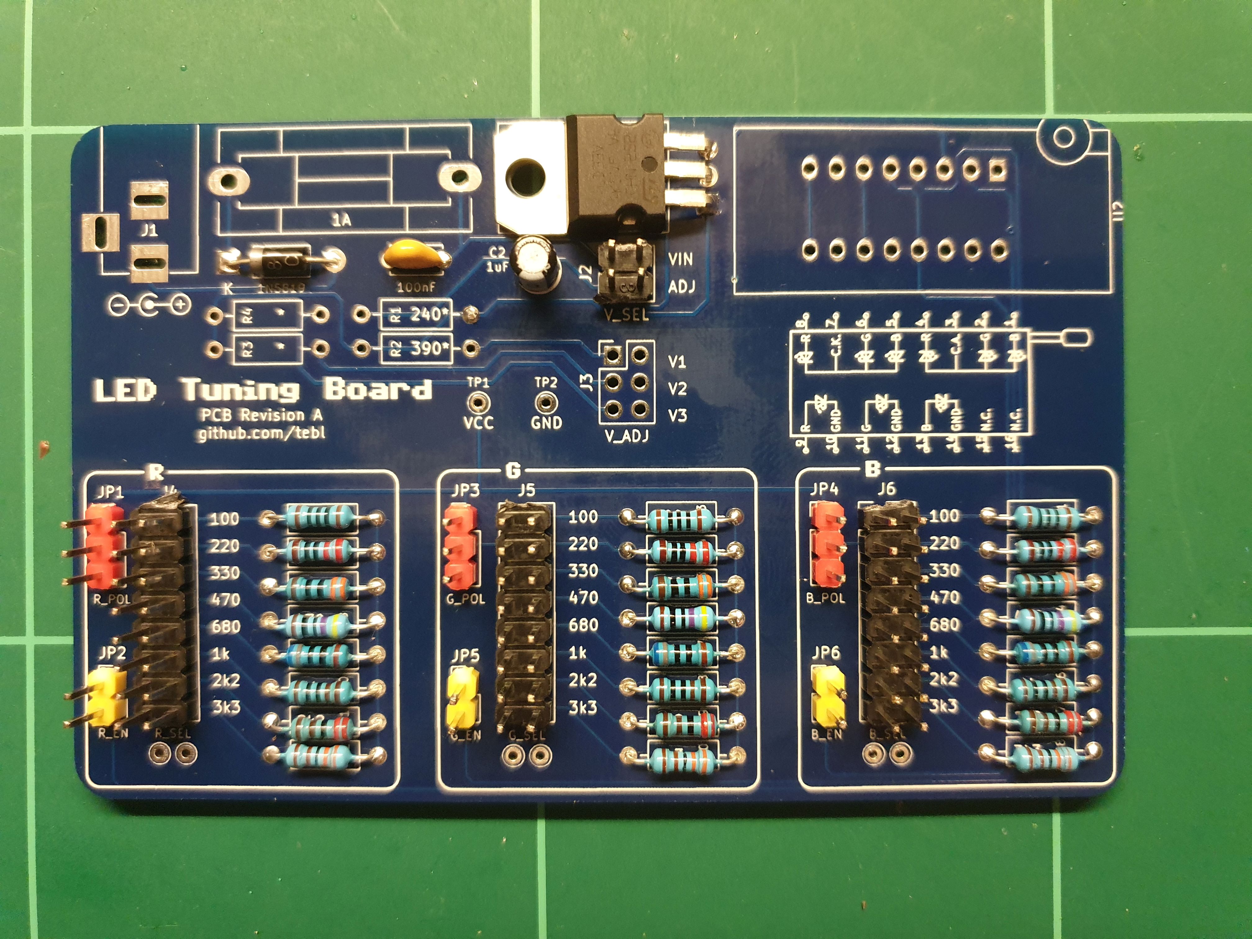
Moving on with the installation, we've then done is to add all of the pin headers that are required. I've tried splashing a bit of colour here and there, mostly so that I remember that the red ones are the ones that requires that we know what we're doing (linking the block to either VCC on top, or GND on the bottom). The yellow are for enabling a block, if you want to measure current usage then you would put your meter on each of these two pins - otherwise, replacing it with a jumper cap. The black are always linked horizontally, choosing a specific resistor value, input voltage or chosen variable voltage.
If you've installed some like it before, you've no doubt already altered your fingerprint by trying to hold to one while doing so. Heat travels, and to put your finger on the other side while soldering it means that your finger will reach the set soldering iron shortly thereafter. They will go crooked, so my method is just to tack them mostly into place then reheat with a better grip afterwards - then solder the others. Perfect result, one *ouch* at a time!
Next step accounts for the rest, so we're just adding a 2.1mm x 5.1mm barrel socket for input power as well as cheap 5x20mm glass fuse holder. As for the latter some of them will come without the plastic shroud and need to be installed with a fuse in it, at least that's what I find to be easiest.
For the pièce de résistance, I'm using the cheapest 16-pin ZIF-socket known to man. I don't know if it remains the cheapest, but it was when I ordered it - and that makes it perfect for abuse on projects such as this one. Just remember to install it with the socket handle pointing towards the right. As for what the socket pins are used for, it's various types of LEDs and the way they're wired can be seen on the illustration below it (in a way that's slightly easier on later revisions).
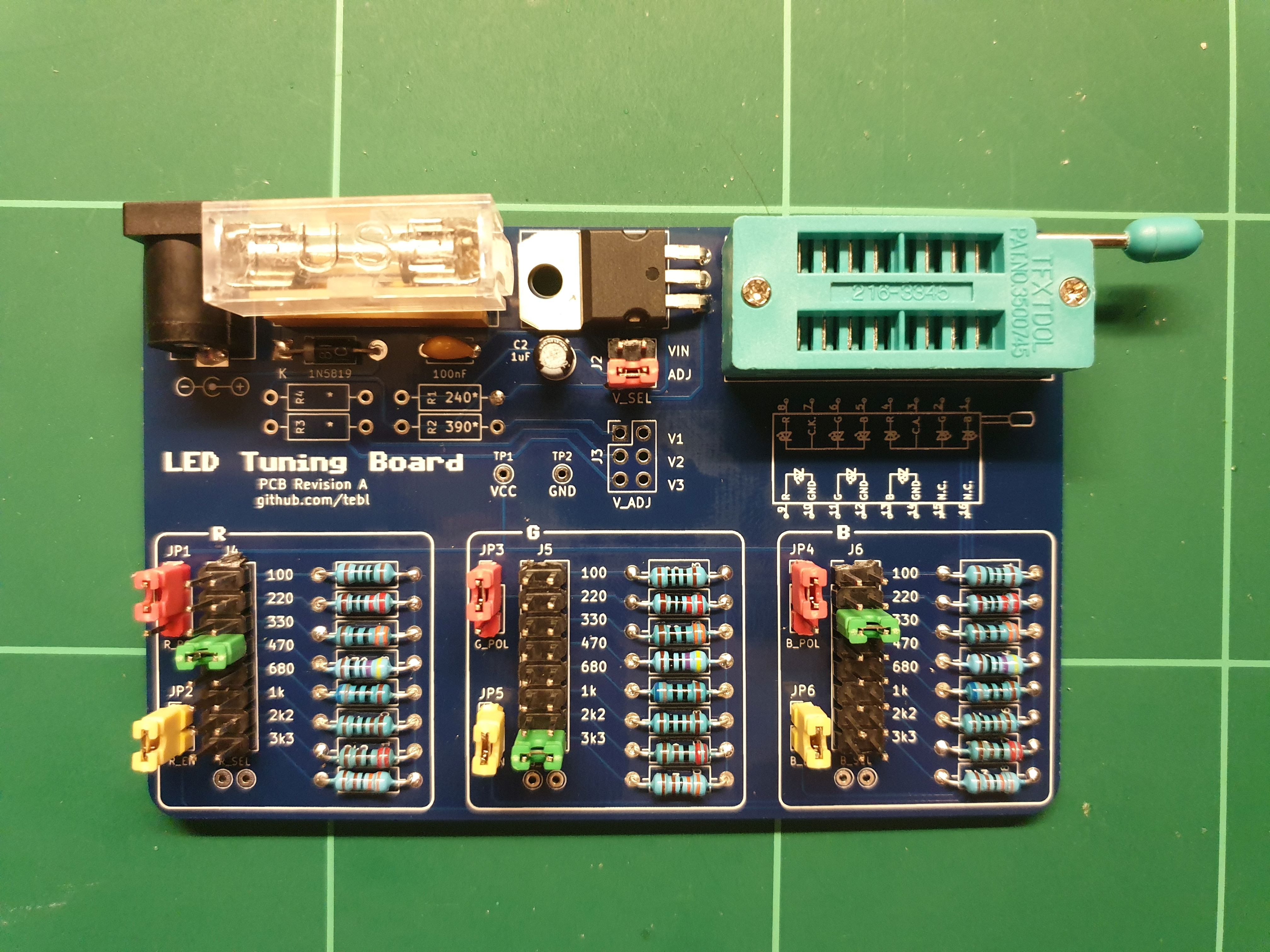
With that we've just added our selection of jumper caps so that'd we have something to play around with. J2 here is set to ADJ so that we're taking our LED power input from the regulator, in the other position we're wired straight to whatever comes through the fuse and the slight drop from the power diode. As for what comes next, just plug some random LEDs into it and start moving the green jumpers, as shown in the picture, up and down until you find your favorite setting.
Congratulations! You've just managed to make it through to the end, a whole thing just to pick a single resistor value to use for your project (or one of mine).
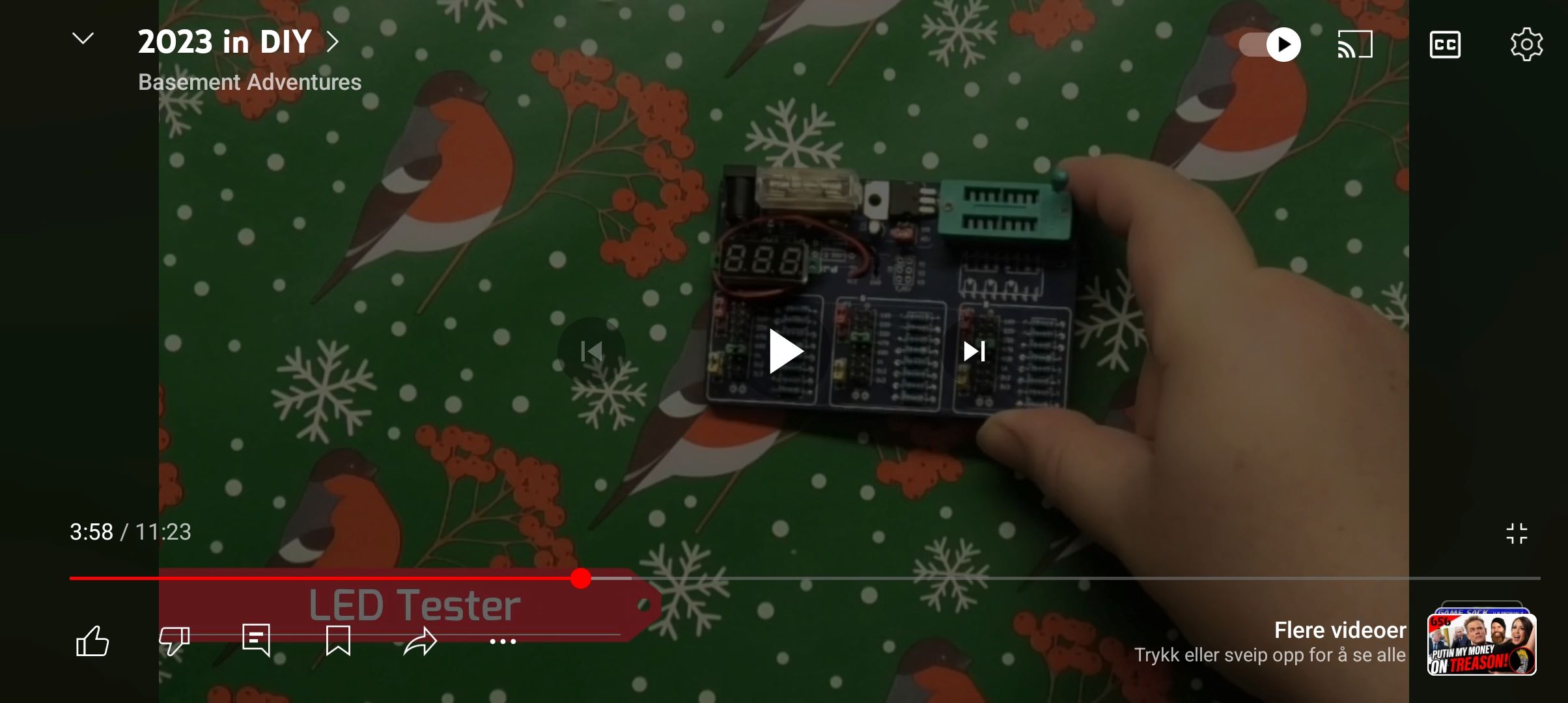
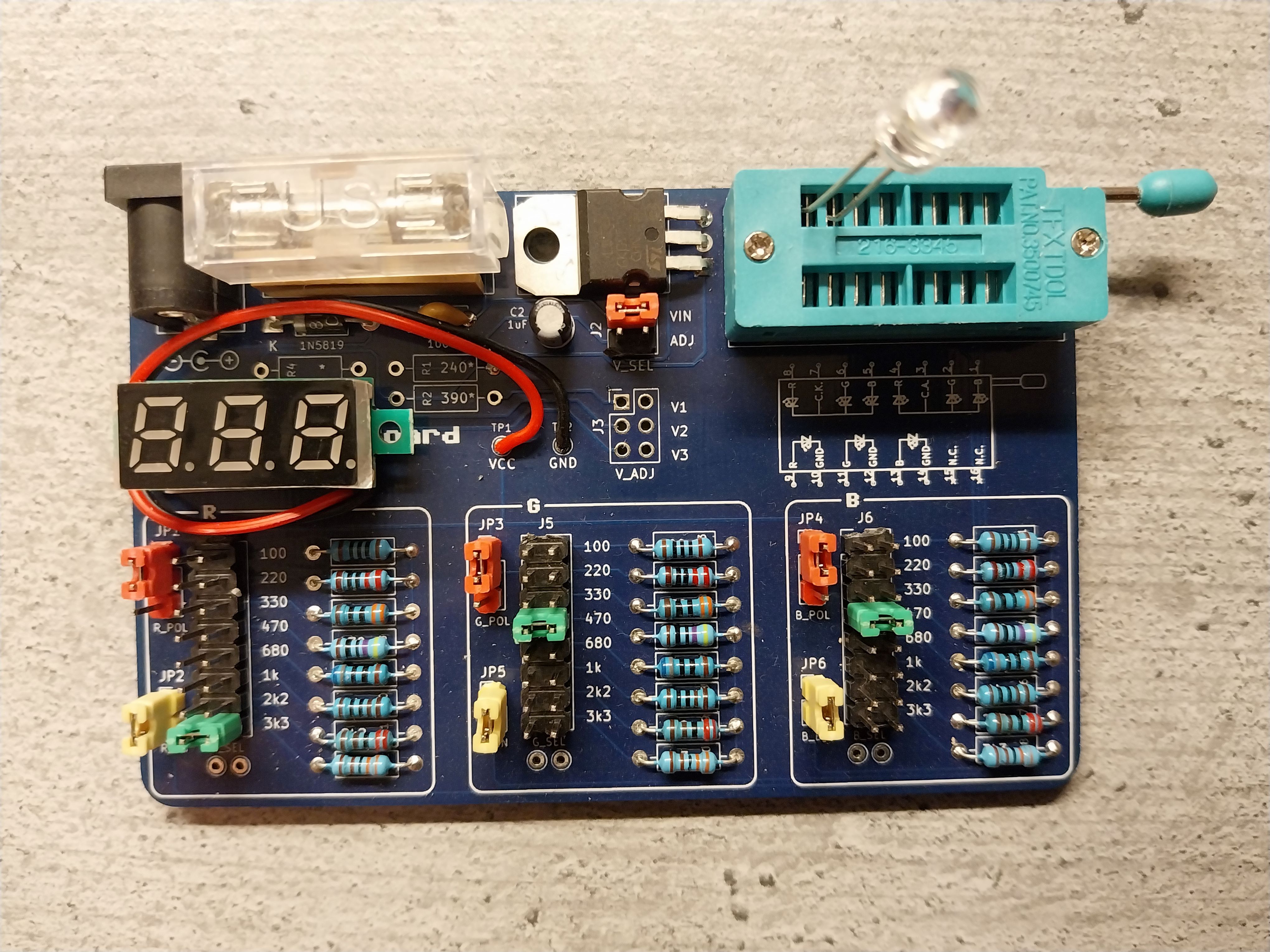
For extra credit, you can also solder one of the cheaply available voltage display modules to the relevant test-points. That way you won't even need to dust off your multimeter when making sure that the voltage has been set correctly, especially when you're using the adjustable voltage regulator. Fix to the board using double-sided tape, wherever you think it'll fit. Here's where I put mine:
The supplied KiCad files should be sufficient as both a schematic and as a starting point for ordering PCBs (basically you could just zip the contents of the export folder and upload that on a fabrication site), the schematic is also available in PDF-format and this is what you'll need to print and work your way through this things don't work as expected after assembly.
Most parts should be easy to get a hold of from your favorite local electronic component shop, but given that I don't have access to such shops where I live so everything was based on whatever I could get cheapest from eBay/AliExpress (free shipping, plan on usually waiting 3-4 weeks though). The list below should be everything you'll need in addition to a workable soldering iron and some 60/40 soldering tin.
Note that some pin references will have a note attached to it, these are found below the table. In particular these are relevant for duplicated references, one for each of the two regulator options described in the documentation (you will only need one set).
| Reference | Item | Count | Order |
|---|---|---|---|
| PCB | Fabricate using Gerber files | 1 | PCBWay |
| C1 | 100nF capacitor (5mm pin spacing) | 1 | |
| C2 *1 | 1uF electrolytic capacitor (2mm pin spacing) | 1 | |
| C2 *2 | 10uF electrolytic capacitor (2mm pin spacing) | 1 | |
| D1 | 1N5819 Schottky diode (DO-41) | 1 | |
| F1 | 5x20mm fuse holder (add 1A fast blow fuse) | 1 | |
| J1 | 2.1mm x 5.5mm barrel socket | 1 | |
| J2 | 2x2 pin 2.54mm dual row straight header segment | 1 | |
| J3 *1 | 2x3 pin 2.54mm dual row straight header segment | 1 | |
| J4-J6 | 2x8 pin 2.54mm dual row straight header segment | 3 | |
| JP1,JP3,JP4 | 1x3 pin 2.54mm straight header segment | 3 | |
| JP2,JP5,JP6 | 1x2 pin 2.54mm straight header segment | 3 | |
| R1 *1 | 240 Ohm resistor | 1 | |
| R2 *1 | 390 Ohm resistor | 1 | |
| R3,R4 *1 | Choose suitable resistor value | 2 | |
| R5,R13,R21 | 100 Ohm resistor | 3 | |
| R6,R14,R22 | 220 Ohm resistor | 3 | |
| R7,R15,R23 | 330 Ohm resistor | 3 | |
| R8,R16,R24 | 470 Ohm resistor | 3 | |
| R9,R17,R25 | 680 Ohm resistor | 3 | |
| R10,R18,R26 | 1k Ohm resistor | 3 | |
| R11,R19,R27 | 2k2 (2200) Ohm resistor | 3 | |
| R12,R20,R28 | 3k3 (3300) Ohm resistor | 3 | |
| U1 *1 | LM317 adjustable voltage regulator (TO-220) | 1 | |
| U1 *2 | LD1117AV33 fixed 3.3v voltage regulator (TO-220) | 1 | |
| U2 | 16-pin ZIF-socket | 1 | |
| Pin header jumper caps, different colours as wanted | 10 |
- These account for the components used when installing a variable voltage regulator, follow the documentation for sizing the resistor without a specified voltage. Also, see *2 for a fixed regulator option.
- These are used for a 3.3v fixed voltage regulator, you would then no longer need those marked *1. For more information see documentation on building the device.