Home
Welcome to the linearStepper-Arduino wiki!
This Arduino library is use to drive stepper motor mounted on a linear device using either a belt & pulley or a thread shaft system. Main feature are :
- All the required operation are interrupt driven, all the functions are non blocking (they will return immediately after the call).
- Many motor could be driven by the lib at their own speed. The class is written so that only the created instance will take some space in the memory (i.e. you don't have to take care of that, simply create one object per motor, the memory management will be done by the compiler)
- Autocorrection of the position to avoid missing steps issues. One limit switch at each end of the linear device will correct the position each time the device reach an extrem position. This feature could be disable for calibration purpose
- Acceleration support : if the linear device should produce high force level, acceleration is recommanded to avoid missing steps. This could be done using dedicated functions.
- Optimized timing : all the critical timing parts have been optimized to allow perfect timing (reducting noise and vibrations, increasing motor torque). Variables are small integer to allow high speed computing, the inconvenient is that the resolution is lower than with float values (1 mm in position)
- Easy to use : the library has been written with a very simple interface, take a look at the description below and at the provided example.
The library required 4 Arduino pins :
- A step pin, connected to the motor driver, each rising edge of this pin will trigger the driver to produce one step. This pin could be any free Arduino pin.
- A dir pin, connected to the motor driver, Low level on this pin will drive the motor to the fore position, high level will drive the motor to the aft position. This pin could be any free Arduino pin.
- 2 limit switches pin (see below). This pin should support pin change interrupt (PCINT pin) The library is designed for stepper motor driver such as A4988 or similar. You can use many stepper driver, the only requirement is that step should occur only during a rising edge of the step pin. The library will put the step pin at low level immediately after that, to optimize interrupt routine timing. A direction pin is required (to be connected to your driver), to inverse the movement of the motor. The library always assume that the aft position of the linear devide is 0, and the fore position is a value that you can set up in the lib (see below). If the motor rotate the wrong way when you send a command to go to the aft for example, please consider to invert wires on driver output phases.
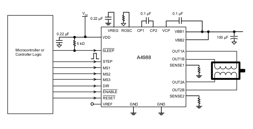
The image above show the A4988 typical application diagram. In our case, the step pin should be connected to the STEP input of the A4988, the dir pin to the DIR input. The motor should be connected to the OUT1A & OUT1B and the OUT2A & OUT2B. Take care to correctly connect one phase on OUT1A & OUT1B, while the other phase is connected to OUT2A & OUT2B. You can destroy the motor and/or the driver if wires are inverted. Anyhow, if you don't know the phases of your motor, you can check it using an ohmeter.
The other input of the A4988 (or other driver) are not driven by the library. You can either connect it to your Arduino board and drive it by your code (or reimplement the missing functionalities by derivate the linearStepper class) or hardware connect them, following the image below for example (!sleep & !reset should be put to high TTL level to operate the driver).
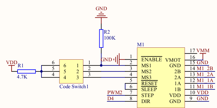
For more information about hardware of stepper driver, consult the datasheet of your driver.
In addition, two limit switches are required (one at each end of the linear device) to run the lib. The chosen pin should support change interrupts:
- 0n the Mega and Mega 2560 only the following can be used for RX: 10, 11, 12, 13, 14, 15, 50, 51, 52, 53, A8 (62), A9 (63), A10 (64), A11 (65), A12 (66), A13 (67), A14 (68), A15 (69).
- On the Leonardo and Micro only the following can be used for RX: 8, 9, 10, 11, 14 (MISO), 15 (SCK), 16 (MOSI). Please check the datasheet of your board for this limitation. The limit switch should be grounded on one side, and the normally close position (NC) of the switch should be connected to the chosen pin of the Arduino board.
Microstepping operation have not been implemented in the library. There is no issue if you plan to drive your motor without microstepping change during execution, but if you plan to, you could either do it in your code (just change the ratio steps / mm each time you change the microstepping configuration), or simply derivate the linearStepper class.
Just as all Arduino library, you should put all the file of the repository in your arduino-x-x-x/libraries/ folder. Create a new directory (name it linearStepper for example) and copy the files. The best way to do this is to create a local repository in the new directory, and to clone the github repository of linearStepper-Arduino. That way, you will be able to update it just by pulling the new version.
- At first, simply construct a linearStepper object
linearStepper motor(stepPin, dirPin, ForeStopperPin, AftStopperPin);. The 4 arguments of the constructor are the Arduino pins connected to the stepper driver and the limit switches. Take care that is you create too many motors, your main loop code will slow down dramatically. - If you already know your mechanical ratio (because you already run the calibration example on the same mechanical device), set the ratio by calling
motor.setRatioStepPerMm(5.83376646f);. - Then you have to give the maximum reachable position for the device by calling
motor.setMaxPosition(1000);. Note that the min position is always 0, the max position is the position of the device when it trigger the fore limit switch. maxPosition is not equal to the distance between the aft & fore limit switch, as the device has its own width. Choose a point on the travelling device, and measure the distance of the two position, when the device trigger the aft stopper, and when it trigger the fore stopper. - Then you will have to set up a speed using
motor.setSpeed(180);. Take care that too high speed will block the motor (it emit a strange noise if it happen), and two low speed lead to lots of noise and vibration. As an alternative you can consider using microsteps. - At this stage, the library don't know the actual position of the device. To inialize the device position, you will have to throw the device to trigger a limit switch. To avoid a stop at an unknown position, you should use either
motor.gotoPosition(MAX_POS);ormotor.gotoPosition(0);. This two particular cases will make the motor move indefinitely until it reach a stopper. Once a stopper is triggered, the library knows the position of the device, you can call all the method of the class. As an alternative, if you don't want to move the motor without any initialization, and if you are sure of the position of the device, you can callmotor.setPosition(521);. Take care that if the device was moved before the library initialization, the position will be wrong until a limit switch is triggered. - Take also care that
motor.setAutoCorrect(false);will disable the auto correction of the fore stopper when the device reach it. Note that when the aft limit switch is triggered, the position is always reset to 0.
To drive stepper motors, timings are very important. This library has been developped using 16Mhz Arduino board. If you use such board and if you are not a confirmed developper, you can stop reading this paragraph.
The main process of this library occur during timer interrupt. To correctly drive the motor, timer2 (an 8-bit timer) was choosen because:
- It is not commonly used by other library, it should be available (as far as I know, just tone lib use it)
- It has the best interrupt priority. The main goal was to have a better priority than USARTs, which have a one byte buffer, so are less timing dependant. The others timers with great priority are timer0, used by all the Arduino delay functions, and timer1, used by several libs.
As we may want to drive several motors at different speed, we cannot just put an interrupt frequency, using either CTC mode, PWM mode, or timer overflow with preloaded values. The process is to trigger a high frequency interrupt and to hook each motor on that pulse.
A too high frequency required lots of ressources (main loop will slow down), and low frequency could limit the "speed resolution" for each motor (it also limit the max speed of a motor). After a lots of tries, the balanced value of 100µs delay betwteen two ISR call was determined.
Without any acceleration and with no load, my motors could be driven up to 680µs per step (without microstepping), after what they stall.
You could have to tweak it for two reasons : your board is not a 16MHz board, and/or you plan to use timer2 for another operation. If you want to tweak it because you want your motor to go faster, please consider that even if you drive your motor with half step, you have to wait 4 interrupts call before triggering one step to the driver.
To give this frequency, we have to compute the correct value in the timer register. Take a look at datasheet and web tutorial if you have to tweak it. Caution After many unfortunate tries, I finally note that the Atmel datasheet is wrong : CTC mode for timer2 is TCCR2B = 100, not 10 ! (i.e. WGM22 only should be set for CTC operations mode, WGM21 in TCCR2A register should be clear).
For convenience, I also put a raw spreadsheet in the repository /extras/timers.ods, you can open it with libreoffice software. You can find different tries and log of acceleration of my motor. Sorry for the "as it" state of this spreadsheet.
Limit switches are managed using pin change interrupt. If you are not using any other pin change interrupt routine (or other library which are using it like SoftwareSerial lib) and if you are not a confirmed developper, you can stop reading this paragraph.
As we don't know which pins are used, all the vectors have been redirected to the same IRQ function, using ISR(PCINT1_vect, ISR_ALIASOF(PCINT0_vect));. This could lead to overloaded vectors, which is illegal for µC. If you plan to use pin change interrupt in your code or another library, please carefully consider on which pin you place your limit switches and redirect only the required PCINT vector (in linearStepper.cpp). SoftSerial lib use the same way, you may have to tweak it if you want to run both library in the same program.
As an example, you can plan to use PCINT1 port for the linear stopper lib. You can find in the AVR datasheet that PCINT1 -> PCINT8-15. You can also determine, using the Mega2560 pinout diagram that PCINT8 = pin 6, PCINT9 = pin 15, PCINT10 = pin 14,... Your limit switch should be connected to one of this pin.
In the linearStepper.cpp file, just change ISR(PCINT0_vect) to ISR(PCINT1_vect), and comment the three lines containing the aliases ISR(PCINT2_vect, ISR_ALIASOF(PCINT0_vect)); should be \\ ISR(PCINT2_vect, ISR_ALIASOF(PCINT0_vect));.
That way, you only need one PCINT vector to run the library, you can drive 4 motors (2 limits switches per motor).
Take care that SoftwareSerial lib use the same process. If you plan to use the both library in the same program, you will also have to tweak SoftwareSerial.cpp file (a UART need only the Rx pin, Tx doesn not handle interrupt).
To do.
linearStepperCalibration.ino is provided with the library to illustrate how to use, and to determine the mechanical ratio step per mm of your device.
The hardware requirements are :
- A stepper driver should be connected to the Arduino board (A4988 or similar). The main requirement is that the driver send a step only in rising edge of the step pin. Arduino step pin should be put in the stepPinX macro.
- Each side of the linear device, limit switches should be provided. Limit switches should be grounded on one side, and the normally close (NC) pin should be connected to the Arduino board. Fore an Aft pin should be put in the ForeStopperPinX & AftStopperPinX macro.
- You can decide where is the Fore and where is the Aft position. Keep in mind that Aft is always 0 position for the library, fore position could be set using void setMaxPosition(const uint16_t maxPosition) method. If the device run on the Fore side when executing a gotoPosition(0), simply inverse the two wire of the same phase at the driver output (i.e. for the A4988, change the connection of the motor, OUT1A <-> OUT1B and OUT2A <-> OUT2B pins )
- This example run with two motors. If you want to try with only one, just comment out the lines containing motorY.
The software process is as following :
- Open a serial monitor with a communication speed of 115 200 bps.
- Accurately measure the travel distance of the linear device. It is not equal to the distance between limit switches, because the device has its own width. Put the value in mm in the setMaxPosition(const uint16_t maxPosition).
- Place any value in the bool setRatioStepPerMm(const float stepPerMm) function. A value of 1.0f is a good start (too high value could lead to go over langage types limits)
- Put a small speed (in mm/s) in void setSpeed(const uint8_t speed). This speed will be wrong at the get-go, as the ratio step / mm is wrong. The motor could block while emitting noise with a too great value. If the value is too small, the motor will move with a lots of vibrations.
Once theses few steps done, you can upload the code in your Arduino board and follow the instruction on the screen (actually it doesn't require any user input).
The process for motorX will be:
- The motor will run to the aft position, until it trigger the limit switch
- After a short while, it will run to the fore position, stopped by the other limit switch.
- As you inform the library of the distance between the aft and the fore position, we will be able to compute the right ratio step / mm. It will be displayed on the serial monitor. Note that this ratio depends only on the mechanical link (pulley diameter or thread pitch), and the microstepping setup. You can make several tries at different speed to check if there is no missed steps. Once done, this ratio could be directly used in your futures program, as long as you didn't change mechanical ratio and microstepping setup (for microstepping setup, you can recompute ratio on the fly).
- As we have now a correct ratio, speed is automatically corrected, but position is not well known because the setAutoCorrect() method is called after the stopper has been triggered. We could do a setPosition(maxPosition), but for demonstration purpose, we will go back to the aft and check that speed is correct.
- The motor will go back to the aft (0 position). A timer is set up to measure the ellapsed time of the travel. Theoretical & measured time is displayed to check if everything is fine.
- For demonstration purpose, the motor will then shift to the middle position, displaying its theoretical and measured position.
- It will then shift 100mm to the aft.
- Finally it will go back to middle position, using a small acceleration rate (see limitations for acceleration rate.)
MotorY is only for demonstration purpose :
- It will start to move will a big acceleration rate.
- If it doesn't reach his limit stopper, it will brake with the same acceleration rate, displaying its position every