This repo documents my own attempt to build a speaker pair as proposed in this YT-video: Building EXCEPTIONAL speakers using MODERN TECHNIQUES.
Note that I will not provide the files owned by DIYPerks. These can be bought according to the instructions on the video. Though, my own additions are stored here and free to use.
There are a couple of instructions on the Zip archive provided in the package, but note that some details can only be found by carefully watching the video. I have added an extraction of the subtitles in a separate file. The file has headings to help one locate a specific topic and I put important information in bold so you din't miss it.
As stated by DIYPerks, Class D amplifiers found on cheap breakout boards are of very low quality mostly because they use clone chips instead of the classic ones of american manufacturers, like the TI TPA3118.
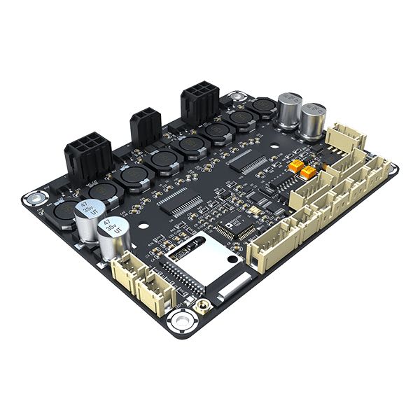
But I found a good alternative manufactured by Sure Electronics (WONDOM), a chinese brand, that targets to quality products and the model is the JAB4. They can be easily found on the popular sound website like:
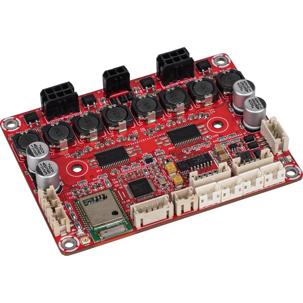
For the american market the same board is sold with the Dayton Audio brand, the KABD-430, and can be found on:
The suggested product has some advantages.
This is a class D amplifier that doubles the energy efficiency, when compared to the initially proposed MOSFET design. It is based on original Texas Instruments amplifier chips, not cheap clones like those found on generic AliExpress-boards.
The PCB design uses high quality components that meets the specification of the Texas Instruments datasheet, so no noise or hiss artifacts are present.
But the most interesting feature is that the board has the Analog Device's ADAU1701 integrated in the design, including necessary power supply circuits.
You just attach a power supply in the range of 10 to 26V and the board works with all necessary stuff, as expected.
Another interesting feature is that the package contains cables long enough to be used on the DIYPerks design.
This board is also more compact. While the original board has 128 x 86 mm, the JAB4 has only 91 x 69 mm. This will allow to put all required electronics in the single compartment.
There are some issues with this alternative.
Class D amplifiers are known to be more sensible to power supply quality. According to the TPS3116/TPS3118 datasheet, the ripple rejection is -70 dB @1 KHz. The XH-M180 TDA7850 proposed on the original design is -80 dB @1 KHz. This is a 10 dB difference!
At the first reaction, bluetooth seems to be a nice feature but, in the current design, all four channels are used for a single channel. Even though the version of the Bluetooth module is 5.0, there is no way to pair both modules into a single logical unit so that Left and Right channels are streamed separately for each box.
To reduce the drawbacks listed before I decided to add some improvements.
For the power supply ripple rejection I've opted to add a DC power supply filter found on AliExpress. My option was to buy 4 pieces of the 4A/25V selection, a pair in parallel, for each box.
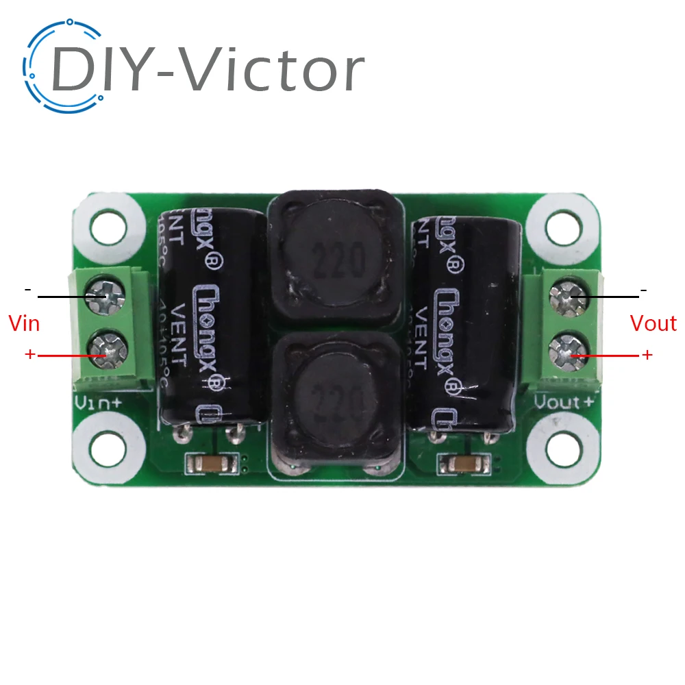
Usually specs for chinese stuff is too exaggerated, I've prefer to use two units in parallel, so that they can work with a good tolerance.
Besides, we double the capacitance, which will help the response to bass transients.
Since the quality of the components may be low, I'va also replaced the 1000µF/25V caps of these boards by Panasonic low ESR caps of the same capacitance/voltage:

Since these have low ESR, means that the internal resistance is in general 10 times lower than regular capacitors, resulting in optimal pulse response when a sudden Bass transient happens.
This one was a bit tricky, since Sure Electronics support ignored my requests, but I've managed to discover a way to deactivate the bluetooth module.
If you look at the board carefully you will notice that U3 is µC that is responsible for activating/deactivating elements when the Stand-By Jumper is used.
It happens that the pin 6 of this chip is responsible for enabling the bluetooth module. So you just have to use a solder iron to de-solder the pin like in the picture below:

Without this connection, the bluetooth module keeps the reset state, which is deactivated.
In the proposal resented above, we have 3 new elements replacing the whole electronics of the original DIYPerks project. Lets build a support plate that fits the original project and combine all elements into a single block.
A 3D STL model is on the repository to build a support plate for the new amplifier board including both DC filters. The repository has a copy of the AmpBase.stl file 3D model. The model looks like this:

Once printed, use M2.5 threaded inserts and populate the holes to fix each board. The four holes on each corner fits the fixation provided in DIYPerks project.
Although the board seems very symmetric, look at the bottom, for the correct alignment:

Note that the original design has a reinforced fixation in form that resembles a water drop. So, consider this element for the correct orientation of the support plate.
This picture shows a populated support plate:

At the left side of the picture you see the amplifier chamber, which I added aluminum adhesive tape to provide some rudimentary shielding for noise reduction.
Considering that the left side is the top of the speakers and the support board is on the correct orientation, like explained before, make your setup like this:
- At the center of the support board you mount the JAB4 amplifier. Note that the black speaker connectors are the left side.
- At the bottom side of the picture you align the inputs of both DC filters, which are marked with Vin- and Vin+ labels.
- Use black cables to connect both Vin- inputs.
- Use red cables to connect both Vin+ inputs (note that I went out of red cables and used a yellow rings to mark the positive cable).
- The same happens with Vout+ and Vout- connections, also red and black, respectively. At the same time connect the power connector cables for power supply of the JAB4 amplifier board (J6 connector).
The mounting is simple like this:

Use the 4 self-tapping screws to fix the support board, the same that were meant to be used in the original design.
To connect the external power supply, use two cables and tie them together on the Vin+/Vin- of the right DC filter board.
For the analog line inputs you have to build a cable that uses a 5-pole JST connector. The connector is above the bluetooth module and has the J13 label.
In my case, I used a stereo coaxial cable where both signal leads are soldered to the RCA internal pin. The outer shielding mesh is the GND and has to be soldered to the outer connector pole.
At the JAB4 side, crimp a JST PH connector with 5 poles using the following signals:
| Pin | Lead / Wire |
|---|---|
| 1 | Line In Signal (any of the two leads) |
| 2 | GND |
| 3 | Line In Signal (the other lead) |
| 4 | Not connected |
| 5 | Not connected |
Note that the pin 1 of J13 is at the top, in this picture.
Sure Electronics offer his own EEPROM writer at a better cost than those generic devices and it is called WONDOM In-Circuit Programmer with UART For PC and you can easily find it:
This is a picture:
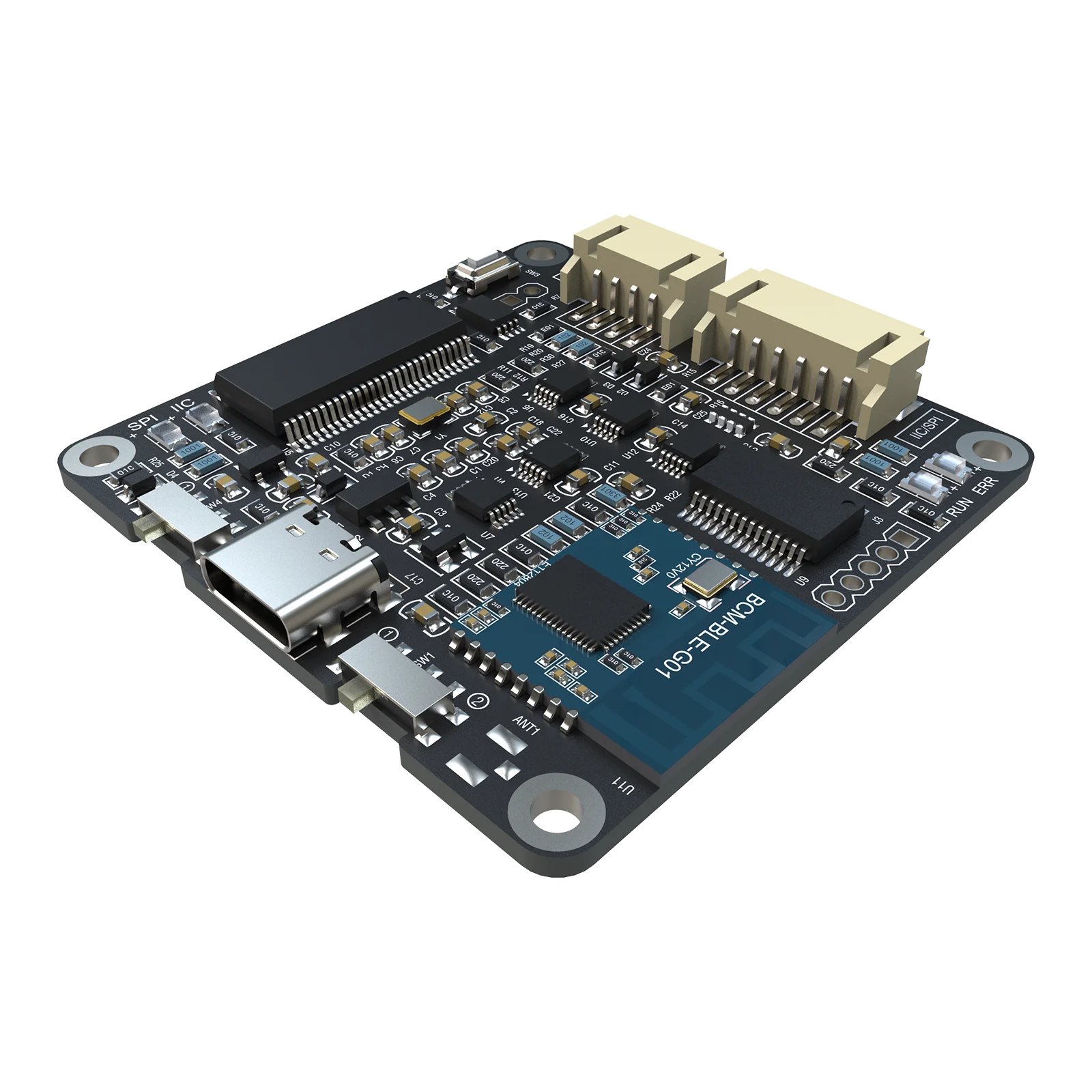
The main advantage is that it comes with a compatible cable and is usually more cheap than USBi clones.
If you already have a Generic USBi device you have to make a cable to connect the leads to a JST PH 6-pin connector J4.
Use the following connection:
| Pin | Signal | USBi Pin / Wire |
|---|---|---|
| 1 | RST | Not connected |
| 2 | +5V | Not connected |
| 3 | GND | GND |
| 4 | WP | Connect to GND to enable EEPROM write |
| 5 | SCL | SCL |
| 6 | SDA | SDA |
Most user complains with connection issues when using the SigmaStudio software, me including.
For a successful experience follow exactly this order:
- Make sure nothing is connected between your PC and the Digital Signal Processor.
- Make sure that the programming cable is only connected to the DSP board. The other end should be left open and not touching any conductive element.
- Connect your USBi/Programmer to your PC and make sure it is recognized. The first time you connect this devices you may have to install special drivers. Check the manufacturer for more information. In the case you are using a WONDOM programmer, you have to follow the instructions on the support pages, because you have to install a brand new firmware.
- Turn the Speaker box on and make sure that the power LED is on.
- Now connect the programmer cable to the In system programmer. If you are using jumpers, than make sure that the GND is the first cable to be connected.
- Now proceed with the software part like shown in the video.