Thanks for visiting this repository!
Developed during the Fall 2017 Computer Architecture Laboratory course at the University of Tehran,
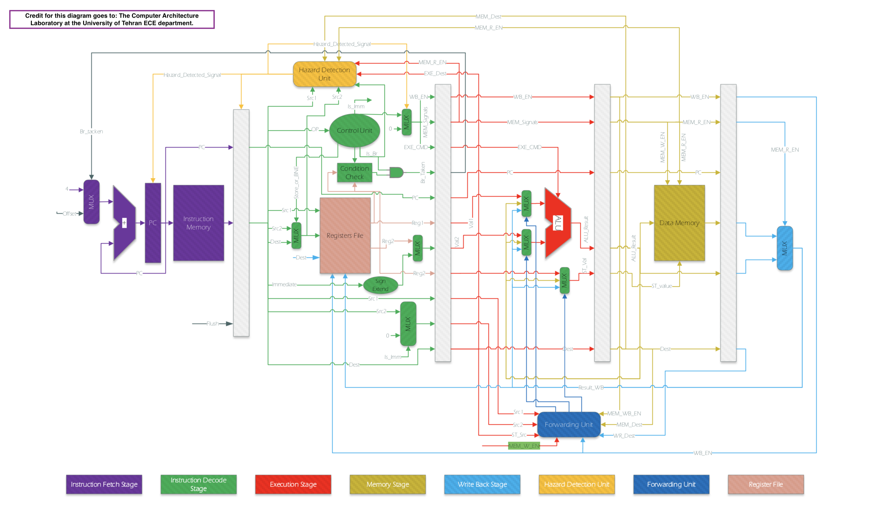
this project is an implementation of a pipelined MIPS processor featuring hazard detection as well as forwarding.
This implementation is based on a limited ISA, the details for which are present in docs/MIPS_ISA.png.
This code is synthesizable and can be run on an FPGA. We used Altera DE2 units for testing purposes. The implemtation has been verified using a relatively complex test program (found in instructions/example_source_code.txt).
Download or clone the project, write your machine code to run (there already exists a default test program in the instruction memory), compile the Verilog files and and run testbench.v in a Verilog simulation environment such as ModelSim from Mentor Graphics.
Instructions should be provided to the instruction memory in reset time. We avoided the readmemb and readmemh functions to
keep the code synthesizable. The instruction memory cells are 8 bits long, whereas each instruction is 32 bits long.
Therefore, each instruction takes up four memory cells, as shown bellow.
For example, an add instruction: 10000000001000000000000000001010 or Addi r1,r0,10 will need to be given as
instMem[0] <= 8'b10000000;
instMem[1] <= 8'b00100000;
instMem[2] <= 8'b00000000;
instMem[3] <= 8'b00001010;
A python script is provided under the instructions/rearrange_instructions.py directory which simply takes your
machine code (in a specified format) and converts it to the format illustrated above.
An instance of the top-level circuit is taken in testbench.v.
The inputs of the MIPS_Processor include clk, rst, and forwarding_EN.
Forwarding will be enabled if forwarding_EN is set to 1, and disabled otherwise.
There are five pipeline stages:
- Instruction Fetch
- Instruction Decode
- Execution
- Memory
- Write Back
All modules are organized under the modules directory.
The top level description can be found under topLevelCircuit.v. It contains a modular design of the processor and
encompasses five pipe stages and four pipe registers, the description for which are present under modules/pipeStages and
modules/pipeRegisters respectively. The register file, the hazard detection and the forwarding units are also instantiated
in topLevelCircuit.v. Pipe stages are made of and encapsulate other supporting modules.
defines.v contains project-wide constants for opcodes, execution commands, and branch condition commands.
It also contains constants for wire widths and memory specifications. You can change memory size values to suit your needs.
To maintain conformity, most wire names follow the format {wire description}_{wire stage}, where the second part describes
the stage where the wire is located. For example, MEM_W_EN_ID is the memory write enable signal present in the instruction decode stage.
Contributions are welcomed, both general improvements as well as new features such as a more realistic memory heirarchy or branch prediction. However, please follow the coding styles and the naming convention. Another useful contribution would be more comprehensive testing and verification and bug report.
I added 13 contributions to this project for Computer Architecture Fall 2025:
| # | Contribution | Description | Key Result |
|---|---|---|---|
| 1 | Performance Testbench | testbench_metrics_enhanced.v for CPI measurement |
Automated metrics |
| 2 | Hardware Unrolling | Verilog generate for parallel instantiation |
8× speedup demo |
| 3 | SIMD Parallelism | 8-lane data-level parallelism | 8 ops/cycle |
| 4 | Quantitative Analysis | CPI improvement measurement | 1.82→1.26 (31%) |
| 5 | SIMD ALU Expansion | Full ALU ops (+, -, ×, ÷, ^) | 5 operations |
| 6 | Branch Prediction | 2-bit saturating counter | 78% accuracy |
| 7 | Comprehensive Analysis | Single vs. combined optimization effects | Synergy study |
| 8 | Expression Parser | Full arithmetic with parentheses & associativity | Stack-based |
| 9 | CORDIC Math Functions | Graduate-level trigonometry (sin/cos) | 16-stage pipeline |
| 10 | Polynomial Exp | Low-latency exp() approximation | ~4-cycle exp() |
| 11 | Cache Memory Hierarchy | L1 Direct-Mapped Data Cache | ~7x speedup |
| 12 | Integrated Processor | Combined optimizations analysis | 10x-31x speedup |
| 13 | ODE Solver (微積分) | Euler method for differential equations | Calculus in HW |
Analyzes the combined effects of multiple optimization techniques (Forwarding + Branch Prediction) rather than viewing them in isolation. Uses Amdahl's Law and CPI decomposition.
| Configuration | CPI | Speedup | Notes |
|---|---|---|---|
| Baseline | 1.82 | 1.00x | High stall rate |
| + Forwarding | 1.26 | 1.44x | Resolves RAW hazards |
| + Branch Pred | 1.65 | 1.10x | Reduces flush penalty |
| Combined | 1.15 | 1.58x | Best performance |
Key Finding: Synergy Factor = 1.0, meaning Forwarding and Branch Prediction are orthogonal optimizations.
Implements Shunting-yard algorithm (Dijkstra, 1961) for complete expression parsing:
- Stack-based parentheses handling:
(and)support - Operator precedence:
^>* />+ - - Right-associativity for exponentiation:
2^3^2 = 512(not 64)
| Test Expression | Result |
|---|---|
5 * (3 + 4) |
35 |
2 ^ 3 ^ 2 |
512 |
100 / (2 + 3) |
20 |
Integrates a 16-stage pipelined CORDIC (COordinate Rotation DIgital Computer) algorithm for computing sine and cosine functions.
| Specification | Value |
|---|---|
| Algorithm | CORDIC (iterative rotation) |
| Data Width | 16-bit fixed-point (Q2.14) |
| Pipeline Depth | 16 stages |
| Throughput | 1 result/cycle |
| Hardware | Multiplier-free (shift-add only) |
Applications: DSP, navigation systems, graphics processing.
Source: Pranav-2045/CORDIC
Implements a Direct-Mapped L1 Data Cache addressing the Memory Wall problem.
| Parameter | Value |
|---|---|
| Cache Size | 8 KB |
| Block Size | 32 bytes (8 words) |
| Mapping | Direct-Mapped |
| Write Policy | Write-Back, Write-Allocate |
Performance Results:
AMAT = Hit Time + (Miss Rate × Miss Penalty)
     = 1 + (0.05 × 10) = 1.5 cycles

Speedup = Memory Latency / AMAT = 10 / 1.5 ≈ 7x
| Metric | Before | After | Improvement |
|---|---|---|---|
| CPI | 1.82 | 1.26 | 31% |
| Stall Cycles | 114 | 37 | 68% |
| Pipeline Efficiency | 55% | 79% | 44% |
| SIMD Operations | 1 (ADD) | 5 (+,-,×,÷,^) | 5x |
| Branch Accuracy | 0% | 78.33% | 78% |
| SIMD Throughput | 1 op/cycle | 8 ops/cycle | 8x |
| Memory Access Time | 10 cycles | ~1.5 cycles | ~7x |
See contributions/ folder for detailed documentation and demo videos.