This is PCB replica of the motherboard of a ZX Spectrum 48k 8-bit computer. It was created on the basis of the last version of the board - "ISSUE 6A" - which was mounted in both Spectrum 48k and Spectrum+. It differs from previous versions mainly by integrating the logic and memory multiplexers in one ZX8401 chip, as well as an improved (especially in comparison with the first versions) the power supply circuit.
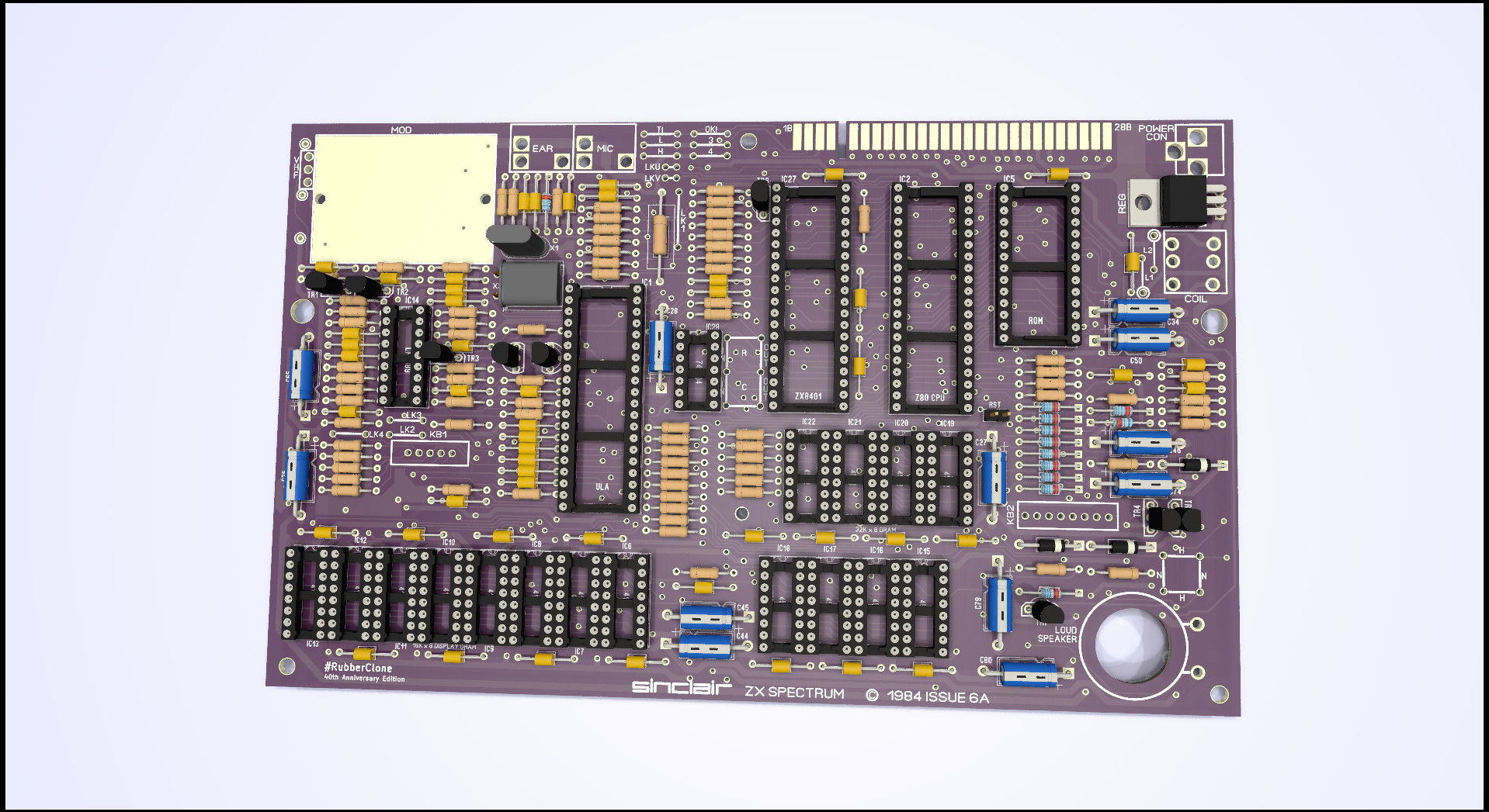
I created it as a tribute to this wonderful little computer for the 40th anniversary of its creation, which for many of us started the adventure in the world of IT technology. Thanks to this replica, you can repair your old ZX Spectrum in which the connector contacts have worn off, tracks and pads have torn off after numerous repairs or have simply been destroyed by rust. After transplanting components to a new board, your Spectrum will not only gain a new life, but also a great look.
- Zilog Z80 processor
- ZX8401 / PCF1306P chip - or its cheap direct replacement built on SMD 74LS chips
- ULA in any version (originally on this board was Ferranti 6C001E-7) or a perfect, modern replacement vLA82
- original ZX Spectrum ROM or EPROM 27C256/27C512 with programmed BASIC binary (requires a slight modification or adapter, e.g. ZXROM 4-in-1)
- lower memory chips type 4116 (e.g. TMS4116-15NL, STC 4116-2N) or a modern SRAM replacement board
- upper memory chips type 4532 or compatible (e.g. TMS 4532-20NL4, OKI M3764-20RS) or modern SRAM module
- LM1889 video modulation chip
- UM1233 RF modulator or S-VIDEO mod board or simple composite output mod
https://docs.google.com/spreadsheets/d/1GlukvK-rJ6DSs6qOmtWpRyai1MQ1hy25GcS9ePSdg4E/edit?usp=sharing
- The resistor and capacitor values in the BOM file are for Ferranti ULA
- For a standard Ferranti ULA - do not populate: R90, C100, C102, C103, leave LK1, LK2, LK3, LK4 - opened
- For SAGA chip - refer the Service Manual
- For TMS chips on upper memory: TI - close, 3 or 4 - depends on the marking on the chip: i.e. TMS4532-20NL4
- For OKI chip on upper memory: OKI - close, L or H - depends on the marking on the chip: i.e. OKI3732L-20RS, for OKI3764 - you can choose which 'half' of its 64kbit you want to use
- ROM settings: N - close for NEC chips, H - for HITACHI chips, for the EPROM adapter - it does not matter
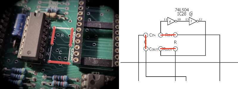
Correct jumper configuration near IC28:
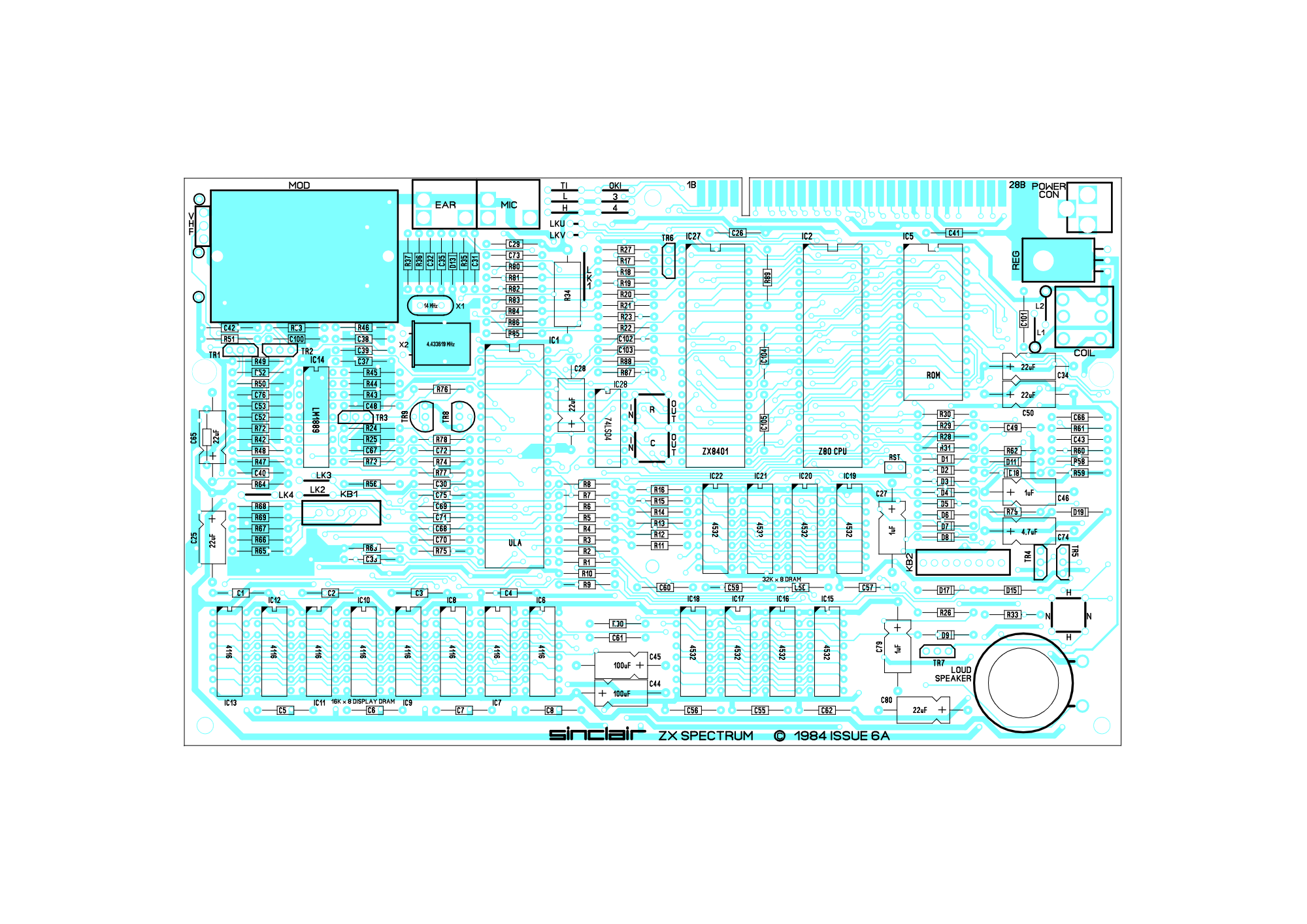
Interactive BOM:

Notice:
I received reports that the board version 1.1 (Dec 2022) has too small holes for the original BA157 diodes (D15 and D17) - I used BA159 diodes manufactured by MIC in the DO-41 package. They have 0.55mm / 0.0215inch thick legs - they fit and work perfectly.
https://github.com/pmandes/zx-spectrum-issue6a-replica/blob/main/Issue-6A-layout.pdf
1.2
- enlargement of all solder holes up to 0.8mm, holes for D15/D17 diodes up to 1mm
1.1
- improving the position of the mounting holes
- correction of all mistakes detected on the prototype
1.0
- prototype
Here you can order ready-made, unpopulated PCBs:
https://www.tindie.com/products/devzine_pl/zx-spectrum-48k-issue-6a-motherboard-replica-pcbs/
- https://mdfs.net/Software/Spectrum/ROMImages/
- https://github.com/brendanalford/zx-diagnostics
- http://blog.retroleum.co.uk/electronics-articles/a-diagnostic-rom-image-for-the-zx-spectrum/
- PCF1306P / ZX8401: https://trastero.speccy.org/cosas/JL/pcf1306p/PCF1306P.html
- PCF1306P SMD: https://www.va-de-retro.com/foros/viewtopic.php?p=182085#p182085
- S-Video Mod: https://github.com/redhawk668/ZX-Spectrum-S-Video
- Composite Mod: https://www.projectavr.com/esp-01-esp-03-flash-prototyping-board/