Example
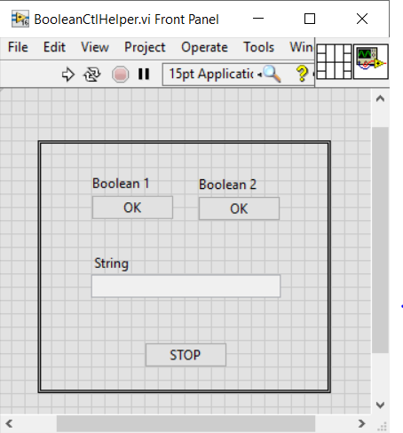
Target Front Panel
Testcase
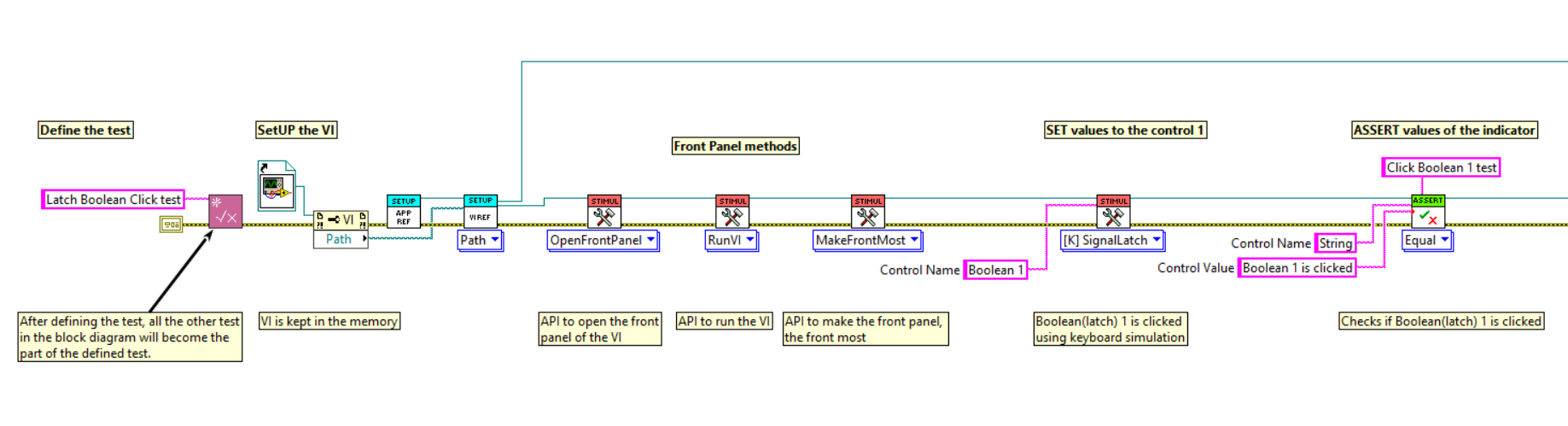
Testcase steps:
Step 1 => Define test
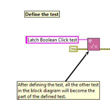
Initially define the test that we are going to perform, so that all the
other test in the block diagram will become part of the defined test.
- In this example, test is defined as "Latch Boolean Click Test".
Step 2 => SETUP
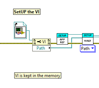
Setup is a stage where we define in which VI we are going to run the test and the VI should be kept in the memory.
- In this example, Static reference of the VI is given.
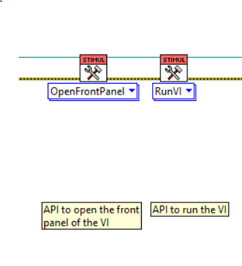
Step 3 => FP Methods
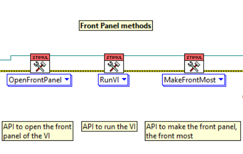
To test certain VI, it should be in a running state or the front panel should be open(sometimes frontmost), hence in this step, the VI is set in desired state.
- In this example, the VI should be in a running state and the front panel should be open.
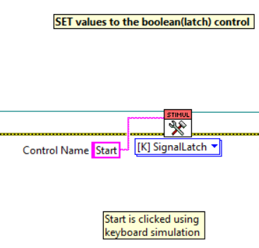
Step 4 => Set Values
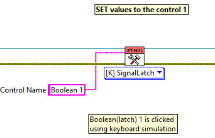
Values to the controls are set in this step.
- In this example, Keyboard simulation is used to set values to the boolean. This is done because the boolean has a latch mechanical action.
Step 5 => Assert Values
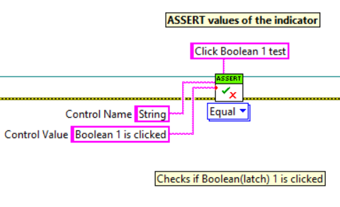
Values are asserted, to check if the desired values are obtained or not.
- In this example, the string indicator is asserted to check if the desired values are obtained, else it fails the testcase.
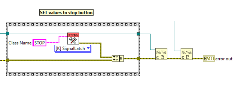
Step 6 => Stop/End the VI
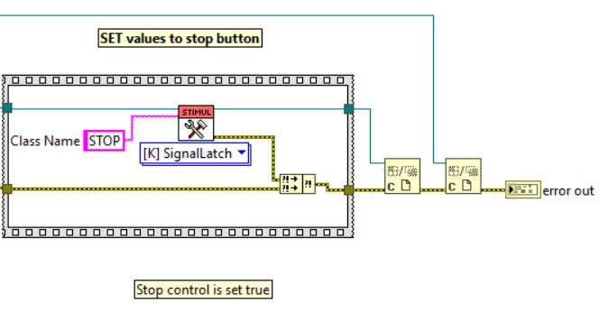
The target VI should be stopped and all the references should be closed at the end of the test.
- In this example, the VI is stopped by setting true to the stop boolean in the VI.
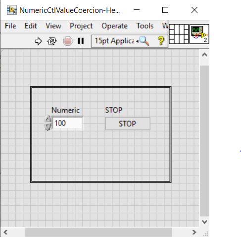
Target Front Panel
Testcase
Testcase steps:
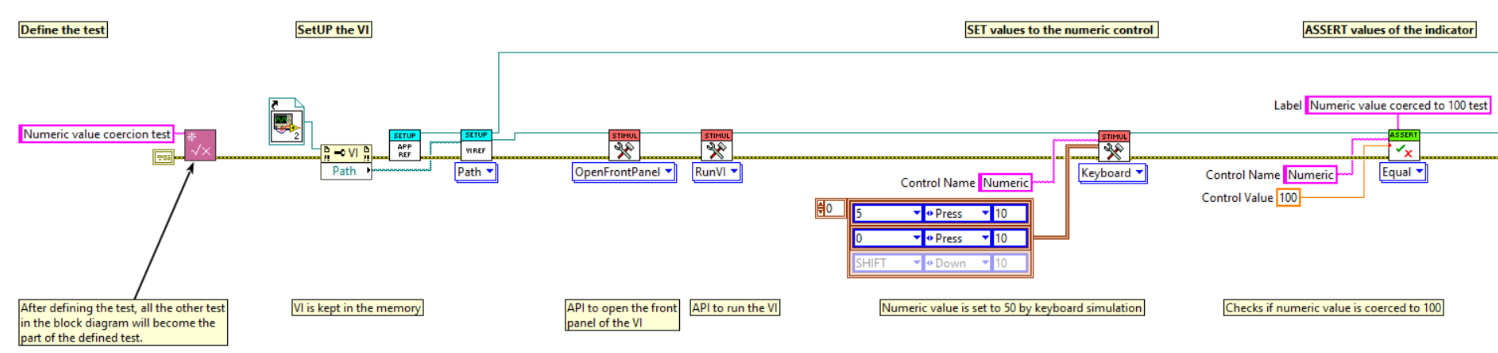
Step 1 => Define test
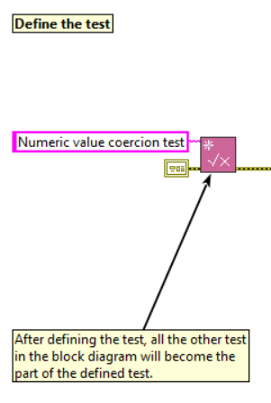
Initially define the test that we are going to perform, so that all the
other test in the block diagram will become part of the defined test.
- In this example, test is defined as "Numeric value coercion test".
Step 2 => SETUP
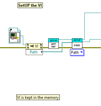
Setup is a stage where we define in which VI we are going to run the test and the VI should be kept in the memory.
- In this example, Static reference of the VI is given.
Step 3 => FP Methods
To test certain VI, it should be in a running state or the front panel should be open(sometimes frontmost), hence in this step, the VI is set in desired state.
- In this example, the VI should be in a running state.
Step 4 => Set Values
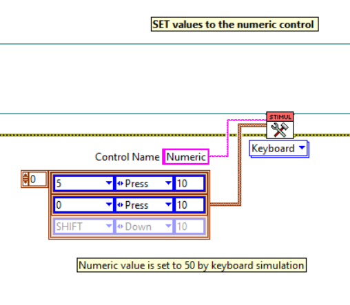
Values to the controls are set in this step.
- In this example, Keyboard simulation is used to set values to the numeric control. This is done because the coercion of limits will not take place, when we set value programmatically using set value nodes.
Step 5 => Assert Values

Values are asserted, to check if the desired values are obtained or not.
- In this example, the numeric control is asserted to check if the desired values are obtained, else it fails the testcase.
Step 6 => Stop/End the VI
The target VI should be stopped and all the references should be closed at the end of the test.
- In this example, the VI is stopped by setting true to the stop boolean in the VI.
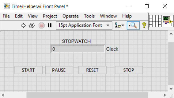
Target Front Panel
Testcase
Testcase steps:
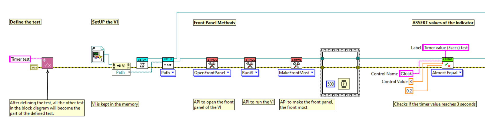
Step 1 => Define test
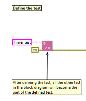
Initially define the test that we are going to perform, so that all the
other test in the block diagram will become part of the defined test.
- In this example, test is defined as "Timer test".
Step 2 => SETUP
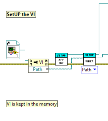
Setup is a stage where we define in which VI we are going to run the test and the VI should be kept in the memory.
- In this example, Static reference of the VI is given.
Step 3 => FP Methods
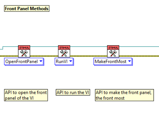
To test certain VI, it should be in a running state or the front panel should be open(sometimes front most), hence in this step, the VI is set in desired state.
- In this example, the VI should be in a running state and the front panel should be the front most.
Step 4 => Set Values
Values to the controls are set in this step.
- In this example, Keyboard simulation is used to set values to the boolean(Start). This is done because the boolean has a latch mechanical action.
Step 5 => Assert Values
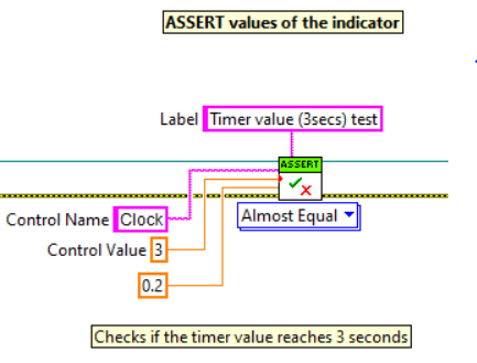
Values are asserted, to check if the desired values are obtained or not.
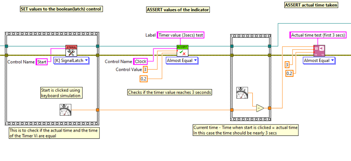
- In this example, the numeric indicator is asserted to check if the desired time values are obtained, else it fails the testcase.
In asserting time value, we can verify if the timer time and the actual time are equal, by measuring time period from start to end.
Example:
Step 6 => Stop/End the VI
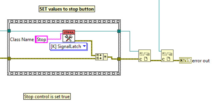
The target VI should be stopped and all the references should be closed at the end of the test.
- In this example, the VI is stopped by setting true to the stop boolean in the VI.